background image

Part Number 040003628 08/13

1-1

Section 1

General Information

General

It is recommended that this ice machine be inspected 
and installed by a qualified service technician. 

Follow all recommendations and instructions for proper 
installation and safe operation of this ice machine.

Model Numbers:

This manual covers the following models:

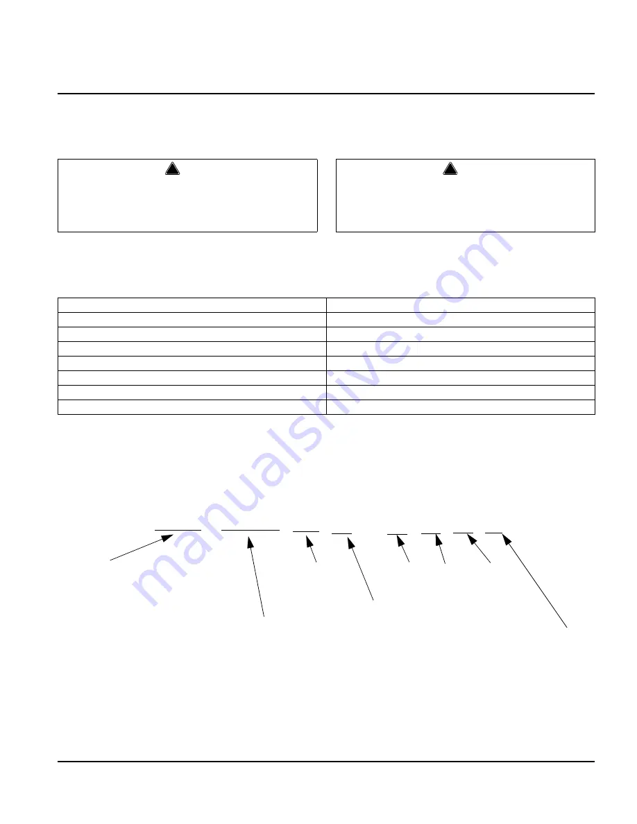
Model Numbers Identification:

UG 040 A C - 2 5 1 F

!

Warning

If you do not understand the procedures or the
safety precautions that must be followed, call your
local service representative to perform the
necessary installation procedures for you.

!

Warning

PERSONAL INJURY POTENTIAL

Do not operate equipment that has been misused, 

abused, neglected, damaged, or altered/modified 

from that of original manufactured specifications.

Self-Contained Air-Cooled

Self-Contained Water-Cooled

UG018A

N/A

UG020A

N/A

UG030A

UG030W

UG040A

N/A

UG050A

UG050W

UG065A

N/A

UG080A

N/A

Ice Machine Model

018= Model 18
020= Model 20
030= Model 30
040= Model 40
050= Model 50
065= Model 65
080= Model 80

A – Air Cooled
W – Water Cooled

Blank: Non-market specific
S: Saudi Arabic
K: Korea
C: China
G: GS approved
E : WRAS approved
B: Brazil 

F= Schuko

G= Blade

Z= No Plug/Bare Lead

I= Oblique Flat Blades with Ground
B = 115V Grounded Power Cord

1= 115V
2= 230V

5= 50Hz
6= 60Hz

1= 1 Phase

Содержание UG018

Страница 1: ...t Number 040002628 8 13 SOTTO Ice Machines UG Models Installation Operation and Maintenance Manual This manual is updated as new information and models are released Visit our website for the latest manual ...

Страница 2: ... e Warning st atement before pr oceeding and wor k carefully Caution Text in a Ca ution b ox ale rts yo u to a s ituation in which you could damage the equipment Be sure to read the Caution statement before proceeding and work carefully Important Text in an Important box pr ovides yo u with information that may help you perform a procedure more ef ficiently Disr egarding this information will not ...

Страница 3: ...ns 2 1 Location of Ice Machine 2 2 Leveling the Ice Machine 2 2 Electrical Service 2 3 VOLTAGE 2 3 FUSE CIRCUIT BREAKER 2 3 TOTAL CIRCUIT AMPACITY 2 3 Water Service Drains 2 4 WATER SUPPLY 2 4 WATER INLET LINES 2 4 DRAIN CONNECTIONS 2 4 WATER SUPPLY AND DRAIN LINE SIZING CONNECTIONS 2 4 Installation Checklist 2 6 Before Starting the Ice Machine 2 6 Section 3 Operation Component Identification 3 1 ...

Страница 4: ...13 Section 4 Maintenance General 4 1 Cleaning the Condenser 4 2 Interior Cleaning and Sanitizing 4 3 GENERAL 4 3 CLEANING SANITIZING PROCEDURE 4 3 Exterior Cleaning 4 4 Removal from Service Winterization 4 4 Section 5 Before Calling for Service Checklist 5 1 ...

Страница 5: ...the necessary installation procedures for you Warning PERSONAL INJURY POTENTIAL Do not operate equipment that has been misused abused neglected damaged or altered modified from that of original manufactured specifications Self Contained Air Cooled Self Contained Water Cooled UG018A N A UG020A N A UG030A UG030W UG040A N A UG050A UG050W UG065A N A UG080A N A Ice Machine Model 018 Model 18 020 Model ...

Страница 6: ... required when requesting information from your local Manitowoc distributor or Manitowoc Ice Inc The model and serial number are listed on the OWNER WARRANTY REGISTRATION CARD They are also listed on the MODEL SERIAL NUMBER DECAL affixed to the ice machine remote condenser and storage bin Model Serial Number Location Model ______________________ Serial Number ______________________ Model Serial Nu...

Страница 7: ...owoc Ice Inc 3 Damage caused by improper installation of the ice machine electrical supply water supply or drainage or damage caused by floods storms or other acts of God 4 Premium labor rates due to holidays overtime etc travel time flat rate service call charges mileage and miscellaneous tools and material charges not listed on the payment schedule Additional labor charges resulting from the ina...

Страница 8: ...General Information Section 1 1 4 Part Number 040003628 08 13 PAGE INTENTIONALLY LEFT BLANK ...

Страница 9: ...ctions General These instructions are provided to assist the qualified installer Ice Machine Dimensions Model L W H UG018 mm 343 450 635 UG020 mm 450 475 650 UG030 mm 450 475 650 UG040 mm 550 550 800 UG050 mm 550 550 800 UG065 mm 700 600 902 UG080 mm 700 600 902 ...

Страница 10: ... chart below for clearance recommendations NOTE The ice machine may be built into a cabinet There is no minimum clearance requirement for the top or left and right sides of the ice machine The listed values are recommended for efficient operation and servicing only Leveling the Ice Machine Levelers are included with all ice machine Legs are an available option 1 Screw the legs or levelers into the...

Страница 11: ...with a strain relief near the terminal strip 3 Verify wiring is contained in the electrical wiring box Warning All wiring must conform to local state and national codes The ice machine must be grounded in accordance with national and local electrical codes Warning RISK OF ELECTRICAL SHOCK FOR H ARD WIRED WIRED WITHOUT A PLUG MACHINE IT MUST BE PR OPERLY GROUNDED AND CONNECTED T O THE FIELD WIRING ...

Страница 12: ... inch drop of run for each meter 3 feet and must not create traps The floor drain must be large enough to accommodate drainage from all drains Run separate bin and water cooled condenser drain lines Insulate them to prevent condensation by temperature WATER SUPPLY AND DRAIN LINE SIZING CONNECTIONS Water Inlet Hose Supplied With Machine 3 4 Female Pipe Thread 2 meters long Drain Hose Supplied With ...

Страница 13: ...ction 2 Installation Instructions Part Number 040003628 08 13 2 5 WATER SUPPLY AND DRAIN LINE CONNECTIONS Water Cooled Condenser Inlet Water Cooled Condenser Outlet Ice Making Water Inlet Drain Electrical ...

Страница 14: ...he rating on the nameplate Are all components installed Has the ice machine been installed where ambient temperatures will remain in the range of 10 43 C 50 110 F Has the ice machine been installed where the incoming water temperature will remain in the range of 10 32 2 C 50 90 F Is there a separate drain line for the water cooled condenser Are all electrical leads free from contact with refrigera...

Страница 15: ...40003628 08 13 3 1 Section 3 Operation Component Identification Water Curtain Water Sump Trough Air Cooled Condenser Evaporator Ice Chute Spray Bar Spray Nozzles Toggle Switch Control board On Off Wash Toggle Switch ...

Страница 16: ... Slide top cover back to disengage the three pins from the front panel BIN DOOR Allows access to the storage bin 1 Remove top cover 2 Slide door up until rear pins align with slot in door tracks 3 Lift rear door pins out and slide door up until front door pins align with slot 4 Lift door out of door track Remove Two Screws Slide Cover Back To Remove Align Door Pins With Track Slots Then Lift Door ...

Страница 17: ...UTE The ice chute is positioned over the spray nozzles and allows the ice to easily fall into the bin It must be firmly positioned over the Spray Bar Assembly with the front edge inside the water trough or the spray nozzles will not be aligned with the spray holes and spray water will fall into bin 1 Grab protruding spray holes on one end and lift up 2 Pivot ice chute and remove 3 To re install ic...

Страница 18: ...ray bar components when necessary 4 To re install spray bar position water inlet tubing on inlet ports and squeeze clips until tight 5 Reposition assembly on water trough seat Nozzles and inserts can be removed for cleaning by unscrewing nozzles Inserts are located inside the spray bar ports The spray bar also disassembles for easy cleaning SUMP DRAIN OVERFLOW TUBE The sump drain overflow tube is ...

Страница 19: ...tpone time has elapsed the harvest cycle is initiated 3 Harvest Cycle The compressor continues to operate and the water pump is de energized The hot gas valve energizes allowing hot gas to enter and warm the evaporator The water valve is also energized aiding with harvest as well as filling up the sump with fresh water for a new freeze cycle at the point of 2 minutes to freeze end board will read ...

Страница 20: ...bes should have a small dimple in the center 2 Cycle times vary according to surrounding air and water inlet temperatures 3 If cubes are not full large dimple raise the dip switch level to increase cube size Allow ice machine to complete three cycles then check cube 4 If cubes are too full no dimple lower the dip switch level to decrease cube size Allow ice machine to operate three complete cycles...

Страница 21: ... end user and service technician should perform and the frequency These figures are the minimum required If the Ice Machine is supplied with hard water more frequent evaporator cleaning should be performed If the condenser air filter is totally blocked after one week more frequent cleaning is recommended X End User S Service Company Caution If you d o not understand the pr ocedures o r the safety ...

Страница 22: ...een the fins If dirt remains A Blow compressed air through the condenser fins Be careful not to bend the fan blades B If dirt or grease remains between fins consult your service representative WATER COOLED CONDENSER AND WATER REGULATING VALVE The water cooled condenser and water regulating valve may require cleaning due to scale build up Low ice production high water consumption and high operating...

Страница 23: ...water sump Allow all water to drain from the sump Replace drain plug Set toggle switch to WASH and circulate for 12minutes Step 9 Wait until the cleaning cycle 12 minutes is complete then place the toggle switch in the OFF position Remove water curtain ice chute water sump over flow tube Drain water from sump and replace tube Step 10 Mix 60 ml of sanitizer with 12 l of water in a plastic or stainl...

Страница 24: ...ervice switch 2 Turn off the water supply 3 Drain the water from the water sump and water pump by disconnecting the water pump tubing 4 Disconnect and drain the incoming ice making water line and disconnect the tubing from the water inlet valve outlet and allow water to drain 5 Blow compressed air in the drain opening and water valve outlet hose then reattach 6 Make sure water is not trapped in an...

Страница 25: ... line thermistor faulty replace the thermistor Control board problem Call for service Freeze cycle long low production Dirty condenser Clean condenser Water temperature too high Connect to a cold water supply verify check valves in faucets and other equipment work properly Refrigeration problem Call for service Shallow incomplete or white ice cubes Ice machine is dirty Clean sanitize the ice machi...

Страница 26: ...Before Calling for Service Section 5 5 2 Part Number 040003628 08 13 PAGE INTENTIONALLY LEFT BLANK ...

Страница 27: ...PAGE INTENTIONALLY LEFT BLANK ...

Страница 28: ...inuing product improvement may necessitate change of specifications without notice Part Number 040003628 8 13 Every new piece of Manitowoc Foodservice equipment comes with KitchenCare and you choose the level of service that meets your operational needs from one restaurant to multiple locations StarCare Warranty lifetime service certified OEM parts global parts inventory performance audited ExtraC...

Отзывы: