18
424WBST Designer Woodburning Fireplaces
87D1506
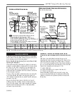
example of Determining Hearth extension
equivalents
To determine the thickness required for any
new
mate-
rial:
COMMON MATERIALS AND FACTORS
MATERIAL
K*
R
MINIMUM
THICKNESS
EH2416
Common Brick
0.458
5.0
1.09 0.50 in.**
0.10 5.46 in.**
(MHSC)
R Value is for 1/2 inch.
* Units of K = BTU/SQ FT/HR
/˚F/IN
** Thickness of Listed Material
FP533ADD
Addendum
6/1/99 djt
8/4/99 changed .2 to .1
one inch to 1/2 inch djt
FP533AD
Fig. 25
Hearth extension material factors.
FP719
STR/CVR finish wall treatments
5/28/98
Wall Covering
Noncombustible
Decorative
Facing
Noncombustible
Decorative
Covering
Seal all cracks
between fireplace
surround and wall
materials with
noncombustible
material.
Seal crack
between fireplace
and hearth extension
with noncombustible
material.
2x4" Header -
Do not notch at
standoffs.
2x4"
Stud
Safety Strips -
Must be overlapped
56O
" minimum.
Hearth Extension
Insulation
Side View
NOTE:
5
/
O
"
air space
between
Outer Dome
and
combustible
materials
5
/
O
"
5
/
O
"
Outer Dome
FP719
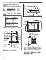
Fig. 26
Finish wall treatments and gap sealing.
NEW
K of new material (per inch)
thickness
required =
X of listed
thickness K of listed material (per inch) material
example for Common Brick
T (new) = 5.0 / 0.458 x 0.50 in. =
5.46 in.
(new required
thickness).
&0
4YPE"FLOOR
DJT
Safety Strips
Must be Over-
lapped 1/2" Min.
Minimum Insulation
Value R-0.94
1/4" Min. Thickness
Combustible
Floor
Noncombustible
Material 7
Z\₂
"
Max. Thickness
Seal Cracks Between Fireplace and Hearth
Extension with Noncombustible Material
Noncombustible
Material
Lower Surround
Fireplace
Hearth
FP1170
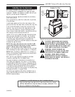
Fig. 27
Hearth extension dimensions.
2”
(51 mm)
2”
(51 mm)
Maximum
14”
(356 mm)
Maximum
10”
(254 mm)
A
A
&0
ALCOVEINSTALLATION
Minimum
33”
(838 mm)
Minimum
36” (914 mm)
6”
(152 mm)
Minimum
Minimum .030 Thick Stain-
less Steel Plate
Insulation with Minimum R
Value of 2.75
Minimum .030
Thick Stainless
Steel Plate
View A
NOTe:
If noncombustible material is not used between the
stainless steel plate and fireplace opening, the steel must
be attached to the front of the unit a minimum of four (4)
places on each piece with sheet metal screws no longer
than 1/2".
NOTe: The size of the insulation and stainless steel
plate must be within limits stated above and covers all
combustible framing material.
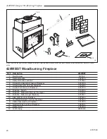
Fig. 28
Recessed installation.
FP1608
Hearth
Extension
Hearth Extension
Noncombustible
Material
(if desired)
Insulation
with Minimum
R Value
of 2.75
Recessed Installation - STR33/36 Only


