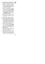
5.2 Resistance measurement
●
Never measure a resistor when
voltage is applied and always
measure it separately, otherwise
the measurement will be inaccu-
rate. For this purpose, solder it out
of the circuit, if required.
1) Set the orange sliding switch (5)
to the upper position
.
Neither the diode symbol
nor
the buzzer symbol
must be dis-
played, otherwise press the but-
ton
(4) so many times until
both symbols disappear.
2) Apply the test prods to the resistor
or to the corresponding meas-
uring points.
5.3 Forward voltage of diodes
●
Never measure a diode when volt-
age is applied and always meas-
ure it separately, otherwise the
measurement will be inaccurate.
For this purpose, solder the diode
out of the circuit, if required.
1) Set the orange sliding switch (5)
to the upper position
.
Press the button
(4) so
many times until the diode symbol
is displayed.
2) Apply the black test prod to the
cathode of the diode and the red
test prod to the anode.
3) The display will show the forward
voltage up to 2 V at a test current
of 1 mA. With 0 V displayed, the
diode has a short circuit. With
Ω
/ /
Ω
/ /
Ω
/ /
Ω
/ /
GB
19


