


AS-i/PROFIBUS Gateway
Connections, Displays and Operating Keys
is
s
u
e
d
a
te
2
2
.6
.2
0
0
1
13
4.2
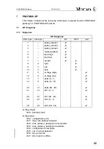
The PROFIBUS Interface
4.2.1
Devices in IP20
The PROFIBUS interface is realized as a 9-pin SUB-D connector, in accordance to
the standard for PROFIBUS DIN 19245. It is placed on the right hand side of the front
panel.
The AS-i/PROFIBUS gateway sends and receives on pins 3 and 8 of the SUB-D sock-
et. The PROFIBUS signal “RxD/TxD-N (data line A)
1
” lies on pin 8, the signal “RxD/
TxD-P (data line B)
1
” lies on pin 3.
The pins 5 (0 V) and 6 (5 V) supply 5 V DC for the bus termination.
Connection samples for the AS-i power supply:
In the wiring schemes above the current through the AS-i master
must not exceed 5 A.
1. If you measure the DC voltage between RxD/TxD-P (data line B) and RxD/TxD-N (data line A), RxD/TxD-P (data line B) is the positive pole
when the bus is silent.
AS-i Master
max. 5 A
PELV according to EN
60950 (Protective
extra low voltage)
AS-i
power
supply
-
+
AS-i Slave
-
+
AS-i Slave
-
+
GND
AS-i Master
max. 8 A
PELV according to EN 60950
(Protective extra low voltage)
AS-i
power
supply
-
+
AS-i Slave
-
+
AS-i Slave
-
+
GND
5
4
3
2
1
9
8
7
6
RxD/TxD-P
(data line B)
RxD/TxD-N
(data line A)
PROFIBUS
Содержание CM4-505-GV1
Страница 2: ......
Страница 6: ...AS i PROFIBUS Gateway The Used Symbols issue date 22 6 2001 6 ...
Страница 8: ...AS i PROFIBUS Gateway Safety issue date 22 6 2001 8 ...
Страница 16: ...AS i PROFIBUS Gateway Connections Displays and Operating Keys issue date 22 6 2001 16 ...
Страница 22: ...AS i PROFIBUS Gateway Operating the AS i PROFIBUS Gateway issue date 22 6 2001 22 ...
Страница 62: ...AS i PROFIBUS Gateway PROFIBUS DP issue date 22 6 2001 62 ...
Страница 68: ...AS i PROFIBUS Gateway Commissioning Tools and Accessories issue date 22 6 2001 68 ...
Страница 77: ......


