Page 12
Page 9
q
5 Minute Epoxy
q
Modeling Knife
q
Straight Edge Ruler
q
Pencil
q
Builder's Triangle
q
(2) Vertical Stabilisers
q
Paper Towels
q
Rubbing Alcohol
q
Epoxy Mixing Sticks
q
Epoxy Mixing Cups
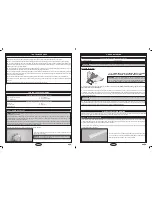
VerTiCAl STAbiliSerS iNSTAllATioN
you'll Need The FolloWiNG PArTS FroM The KiT:
you'll Need The FolloWiNG ToolS ANd SuPPlieS:
STeP 1: AliGNiNG The VerTiCAl STAbiliSerS
q
Cut away the covering material from over the two vertical stabiliser mounting
slots in the top of the wing. Each mounting slot is 3/16" (5mm) wide and 3-3/8"
(86mm) long. The back edge of each mounting slot is located 1-1/8" (29mm)
in front of the elevon hinge line and the centre of each mounting slot is 2-1/2"
(64mm) out from each side of the radio compartment.
q
Push one vertical stabiliser down into one mounting slot, then draw a line on
each side of the vertical stabiliser where it meets the top of the wing. Draw an
outline onto the top of the wing around the base of the vertical stabiliser, too.
warning
When cutting through the covering to remove it in the next step, cut with only enough pressure to cut through only the
covering itself. Cutting down into the balsa structure could weaken the vertical stabiliser and cause it to fail during flight.
q
Remove the vertical stabiliser and cut away the covering material from both
sides of the vertical stabiliser and from the base of the vertical stabiliser, too.
q
Carefully cut away the covering material from within the outline you drew
on top of the wing.
q
Glue the vertical stabiliser into place, using 5 minute epoxy. Wipe away any
excess epoxy and hold the vertical stabiliser in place until the epoxy has
set up.
IMPORTANT
Use a builder's triangle to make sure that the vertical
stabiliser is perpendicular to the wing.
q
Repeat the previous procedures to align and install the second vertical
stabiliser on the other half of the wing.
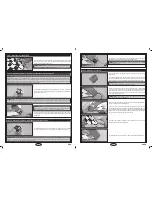
STeP 2: iNSTAlliNG The VerTiCAl STAbiliSerS
q
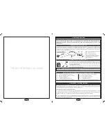
Enlarge the hole in one servo arm that is 3/8" (10mm) out from the centre
of the servo horn, using a 1/16" (1.6mm) diameter drill bit.
q
Install the Z-Bend in one pushrod wire into the hole that you enlarged in the
servo arm.
+
The pushrod wire should be orientated on top of the servo arm.
q
Centre the elevon servo, then install the servo horn onto the servo, making
sure that the servo horn is centred and
pointing out
toward the wing tip.
q
Install the servo horn retaining screw to secure the servo horn to the servo.
q
With both the servo horn and the elevon centred, thread one clevis onto the
pushrod wire and snap the clevis into the
outermost hole
in the control horn.
q
Remove the masking tape and double-check that both the servo horn and
the elevon are still centred. If necessary, thread the clevis in or out to centre
the elevon, then move the elevon up and down several times to ensure proper
movement.
q
Use a couple of pieces of masking tape, taped between the elevon and the wing, to hold the elevon centred.
q
Repeat the previous procedures to install the second elevon control linkage
onto the other half of the wing.
q
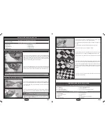
Thin and Thick C/A
q
# 2 Philips Head Screwdriver
q
Modeling Knife
q
Scissors
q
Electric or Hand Drill
q
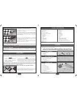
(1) Cowling
q
(1) Landing Skid
q
(2) Plywood Spacer Plates
q
(4) M3 x 12mm Machine Screws
q
(4) M3 x 18mm Machine Screws
q
(4) M3 Flat Washers
q
(4) M2 x 10mm Washer-Head Wood Screws
q
1/16" (1.6mm) Drill Bit
q
Straight Edge Ruler
q
Pencil
q
220 Grit Sandpaper with Sanding Block
q
Masking Tape
lANdiNG SKid ANd MoTor iNSTAllATioN
you'll Need The FolloWiNG PArTS FroM The KiT:
you'll Need The FolloWiNG ToolS ANd SuPPlieS:


