


6
1. Installing the Keel & Stem
Like the bulwarks, the model keel is modi-
fied from the real boat as can be seen on the
plans. The model keel is 1/16" deep x 3/32"
wide basswood. Fit it from Station 10 for-
ward up to the heavier pipe stem piece
which starts just below the waterline. For the
curved portion of the keel, steam bend the
strip or cut it out of a wider sheet of 3/32"
thick wood.
On the real boat the heavy stem is a round
pipe. It is actually fitted over the keel bar
which goes up to the deck. If you have not
done so yet, cut or sand in the notch for the
stem, 1/32" deep. For the heavy stem, add
either a 1/8" diameter dowel. Or a 1/8"
square basswood strip. For the square, sand
the forward side round and sand the back
edges down to the hull. Use wood filler as
necessary to smooth out the joint between
the stem and hull (Figure B-1).
2. Installing the Sternpost, Prop
Shaft Tube Fairing, & Propeller
The sternpost is a 3/32" thick laser-cut wood
part. This is actually part of large forging at
the stern of the real boat that includes the
stern tube. Glue this part to the hull. If it is
not the same width as the hull you have
carved from Stage A, sand the hull flush with
the laser-cut part, or if necessary add wood
filler on the hull so the two will fair. Next,
add the shaft tube fairings on both sides. Cut
these from basswood. Shape the inboard
sides to the hull shape. The outer faces
should be parallel to the hull’s centerline. On
the real boat this is just a hump in the hull
plating that covers the stern tube which
would protrude thru the hull if not covered.
Install the propeller. The prop has a shaft
piece that should fit in the slot in the laser-
cut sternpost . You may need to shorten the
shaft on the prop, or drill a hole at the slot
deeper into the hull (Figure B-2).
3. Installing the Rudder Skeg
& Rudder
As noted in Paragraph 1 above, the keel was
installed forward of station 10. Aft of Station
10 you will add the 3/32" thick laser-cut rud-
der support skeg which extends beyond the
hull. If you have not yet carved the notch for
the skeg, do so now. The bottom of the skeg
should be in line with the bottom of the keel.
Drill a hole in the hull for the upper end of
the rudder stock. At the end of the laser-cut
skeg (part 1), add the laser-cut block (part 2)
which has a hole for the lower end of the
rudder stock. Round the outer edges of the
skeg per the plan.
The rudder is a Britannia casting with the
stock already molded in. Fit the upper end
in the hole in the hull, then in the skeg, and
finally glue the skeg to the hull. You will
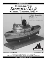
STAGE B:
COMPLETING THE BASIC HULL STRUCTURES
FIG. B-1 KEEL & STEM
FIG. B-2 STERNPOST, FAIRING
& PROP
FIG. B-3 RUDDER SKEG
& RUDDER
FIG. B-4 BULWARK DETAILS
ROUND EDGES
NOTCH
FOR STEM
CUT & ADD
WOOD FILLER
FOR CURVED
BOTTOM END
3/32" x 1/6" KEEL
BACK TO STA. 10
LASER-CUT
PART
KEEL
FAIRING
SHAPE
TO HULL
RUDDER CASTING,
CUT-OFF SHAFT
TO FIT HOLE
LASER-CUT
SKEG
PART 2
ROUND
EDGE
LASER-CUT
SKEG
PART 1
PROP CASTING
NOTCH FOR SKEG
QUARTER BITT
CASTING
CAP RAIL
TYPICAL
BRACKET
TYPICAL
STIFFENER
HAWSE PIPE
LIP CASTING
CHOCK CASTING
ADD WOOD FILLER
USING DOWEL
USING
1/8" SQUARE


