


2. Control Unit Installation
2.1 Mechanical
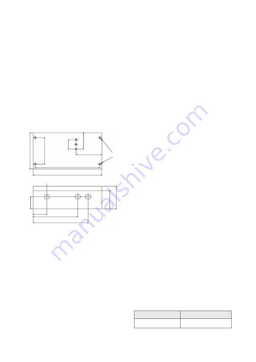
The control unit is supplied with three holes drilled in the
bottom (longer) side of the box. Two glands are supplied
for the power input cable and relay output cable. The
sensor is normally supplied fitted with a suitable gland
on the cable. Two further holes can be drilled in the
bottom side of the box should these be needed: it is
recommended that the circuit board is removed whilst
drilling extra gland holes.
Determine suitable mounting location with regards to :
a) Surface composition / load bearing capacity
b) Cable length restrictions
c) Accessibility for servicing
All cable connections are made to the terminal blocks
along the bottom edge of the pcb (see fig.5). Release
the terminal screw before inserting the wire.
Fig. 3 MCU200 housing dimensions
2.2 External Connections
Protection for permanently installed equipment
NOTE: This equipment is regarded as permanently
installed equipment and must be wired up using
suitable cable for the current and voltage specified. A
suitable switch or circuit breaker must be included in
the installation and this should be in close proximity
to the equipment and marked as its disconnecting
device. A suitable fuse rated at 3A must be fitted in
the supply. Each relay circuit must be protected by a
fuse not exceeding the maximum rated current for the
relay as specified in the manual. As S/C current on the
transformer secondary is in the order of 70 mA and the
transformer thermal fuse will not operate for at least 17
minutes (as tested) a smaller value mains fuse (63mA)
should be agreed upon.
Two cables are required per sensor. The RG178 should
be used where the cable itself is subject to temperatures
exceeding 74°C.
Page 5
120
88
188
200
31
54
75
mounting
holes
1.015
40
140
130
160
75
60
(i)
AC Mains
is connected between the “N” terminal
for neutral and one of the “115V” or “230V” terminals
depending on the voltage supply available - BEWARE -
the terminal not connected externally will be “live” once
the transformer is powered via the other terminals.
(ii)
Protective earth
NOTE: A protective earth should be used for all
applications
(iii)
The DPCO relay
has two sets of contacts. These
are labelled:
Set 1:
NC1
- Normally closed
C1
- Common
NO1
- Normally open
Set 2:
NC2
- Normally closed
C2
- Common
NO2
- Normally open
R
elay warning
CAUTION: If the relay is connected to external
hazardous live (mains) circuits then external circuits
(such as signal circuits) with accessible parts and/or
basic insulation only MUST NOT be connected to the
relay.
(iv)
The Sensor
connections are labelled “1”, “E” for
the receiver crystal and “2”, “E” for the coax cable to the
transmitter crystal. The screens of these coax cables
are connected to the terminals marked “E”.
(v)
The Auxiliary Input
is a terminal which can be
connected to a “push to reset” button to achieve a
latching alarm, or to another Mobrey control unit, to give
a pump control from the MCU200 unit relay output. If a
short circuit is connected between terminals 3 & 4, the
MCU200 relay, once de-energised, is held de-energised.
Even if the sensor attached to the MCU200 changes
state, to that which should energise the output relay, this
relay will not energise until the link between terminals 3
& 4 is broken in the circuit external to the MCU200. See
section 3.3.
2.3 Switch Settings in MCU200 Series
(i)
Gain switch
(and potentiometer): See section 3.
(ii)
Frequency selection
This slide switch is labelled “FREQ” and is located
between the sensor terminal block E2, and the Aux input
terminals. This selects the operating frequency of the
MCU200 oscillator, which is either 3.7MHz (switch in the
'up' position) or 1 MHz, (switch to the down position).
The ex-factory setting is to 1 MHz. The setting required
is dictated by the sensor type connected to the control
unit. Usually these are:
Fig. 4 Sensor frequencies
1MHz sensors
30*S, 33*S
3.7 MHz sensors
40*S, 43*S, 44*S