© MOBATIME
9 / 16
800945.06
•
Connect the conductors to the terminal block on the clock body, in accordance with
the descriptive nameplate (chapter 2.5). Give an appropriate shape to the
conductors or cut them off at a length which does not obstruct the mounting of the
clock into the clock body.
•
Carefully shape all incoming cables into the clocks and secure them by screwing
the cable clamp.
•
Mount the connectors to the cable of the temperature sensor, to the keyboard
cable, Ethernet cable or the RS 232 and RS 485 interface connectors, if these are
used.
•
Push the temperature sensor connector, the keyboard connector, Ethernet
connector or the RS 232 and RS 485 jacks into the corresponding terminals on the
control PCB (DC user manual chapters 2.8, 2.9). Check the marking of the jack-
plugs, in order to prevent their mix-up.
•
Connect the interconnecting cables into the corresponding terminals on the clock
control PCB. Reconnect the earth wire to connect the clock body to the front panel.
•
Put the front panel into the clock body. Care should be taken when placing the
cables between the clock body edge and the back side of the display front panel,
so as not to nip them.
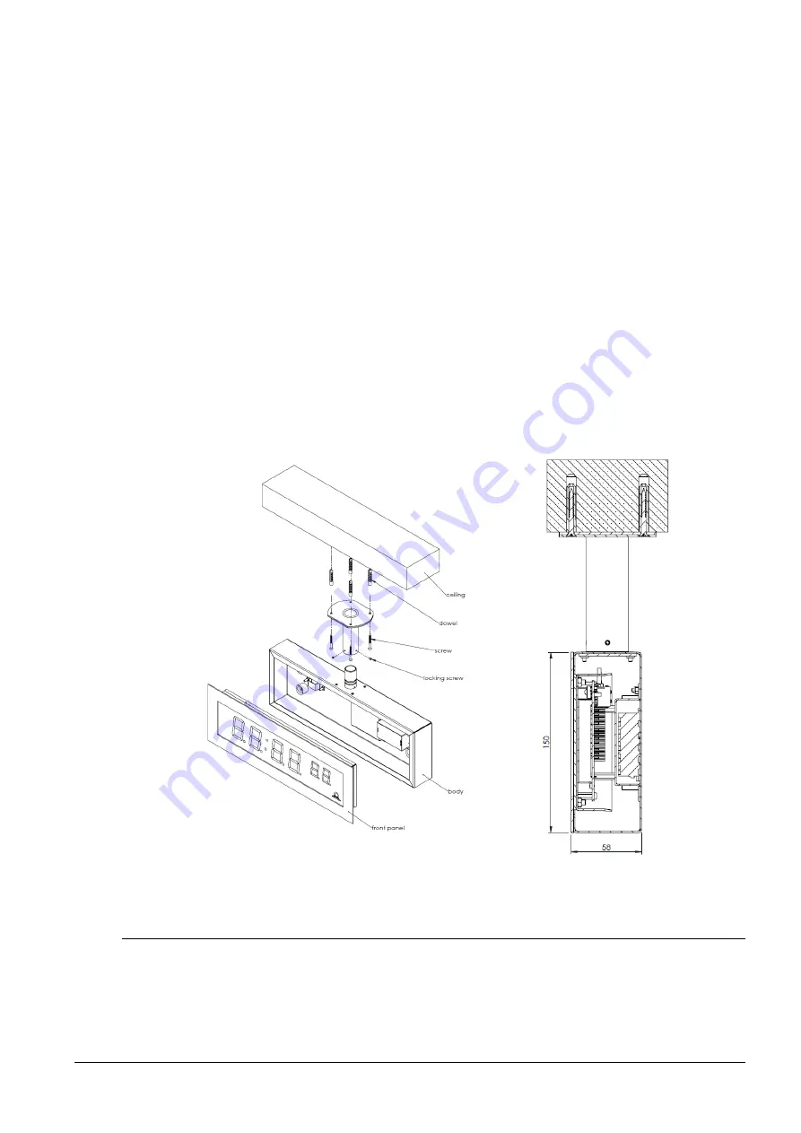
SLH-DC..N.S
cut
2.4 Flush mounting single-sided stainless-steel clock
•
The clock consists of two parts. Visible front stainless-steel panel with display and
back stainless-steel body with connecting terminal block. Both parts of the clock
are held together by neodymium magnets.
•
Remove the front panel from the clock body.
The panel is held by magnets, you
need to use a relatively high force to remove it.


