


34
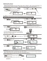
Turn off the remote controller.
Hold down 2 buttons simultaneously for 2 seconds: the
A
and
B
buttons to set the modes 01 through 14, and the
J
and
B
buttons to set the modes 15 through 28.
The “ ” will flash for a while and show “--” as below.
Set the outdoor address.
Press the [
buttons (
and
) to select the desired
address. The address changes from "00" to "15".
If the “ ” and temperature displays flash “
88
” for 2 seconds and stop flashing, this seems to be an error. Check for noise source or interference around the
transmission path.
Note: If the operation is made incorrectly before completion, finish operation by going to the step
0
and restart from the step
2
.
Set the indoor unit No.
Press the
D
button to flash “--“ in the unit No. display .
Press the buttons( and ) ) to indicate the indoor unit
No. in turn such as 00 → 02 → 03 → 04 → AL.
Select the unit No. to which the function selection applies.
•
To set the modes 01 through 06 or 15 through 22, select “00”.
• To set the modes 07 through 14 or 23 through 28,
select “01” or “02”.
Confirm the address and unit No.
Press the
E
button to confirm the address and unit No.
After a while, the mode No. display will flash “
--”.
When the address and unit number are confirmed by pressing the
button, the corresponding indoor unit will start fan operation. This
helps you find the location of the indoor unit for which you want to perform function
selection.
If the temperature display flashes “88”, this indicates that the selected address
does not exist in the system. Or, if the unit No. shows “F” and the address flashes,
this indicates that the selected unit No. does not exist. In this case, set the correct
address and unit No. at the steps
2
through
3
.
Select the mode number.
Press the [
and ) to select the desired mode
number.
(Only vaild mode numbers can be selected.)
Select the setting No. in the selected mode.
Press the
G
button to flash the applying setting
No. Check the current setting No. here.
Press the
F
and to select the desired setting No.
Confirm the settings made at the steps
3
through
7
.
Press the
E
button to flash the mode No. and setting No.,
and to start registration.
The mode No. and setting No. stop flashing to confirm the settings.
If the mode No. or setting No. shows “---” and the temperature shows “ ”, this seems to be a transmission error. Check for noise source or interference around the
transmission path.
To make additional settings in the FUNCTION SELECTION screen, repeat the steps
3
through
8
.
Note. After setting the modes 07 through 14, the modes 23 through 28 cannot be set continuously, or vice versa. In this case, after completing the settings for the
modes 07 through 14 or 23 through 28, go to the step 10 to finish setting, and restart setting from the step 1.
At this point, wait for 30 seconds or more before restarting setting. Otherwise, the temperature may indicate “
88
”.
Exit the Function Selection screen.
Hold down 2 buttons simultaneously for 2 seconds or more: the
A
and
B
buttons for the modes 01 through 14, and the
J
and
B
buttons for the modes 15 through 28.
After a few seconds the Function Selection screen returns to the OFF screen.
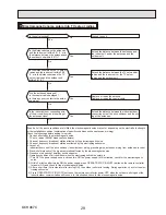
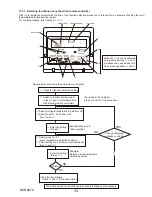
[Operating Procedure]
Check the function selection settings.
Changing the function selection settings for each mode will change its relevant mode function. Perform steps
2
through
7
to check all the function selection settings,
and write down the current settings in the Check column of the function selection <Table 1> in the chapter 11-1, and then change the settings as necessary.
For the initial settings, refer to the <Table 1> in the chapter 11-1. The following is the procedure to operate the remote controller internal sensor.
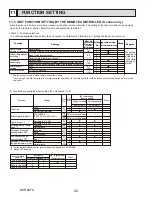
FUNCTION
SELECTION
FUNCTION
SELECTION
MODE
TEMP] buttons (
MENU
FILTER
TEST
TEST
Address
display section
Unit number
display section
Mode number
display section
Mode number
display section
Mode number 02 = Indoor temperature detection
Setting number display section
Setting number 3 = Remote controller's internal sensor
Setting number 1 = Indoor unit's internal sensor
CLOCK]
Outdoor
unit
Indoor unit
Fan mode
Main
Remote controller
Confirm
Note: When changing the initial settings in the FUNCTION SELECTION screen, be sure to write down the changes by putting a circle in the
Check column of <Table 1>.
FUNCTION
SELECTION
OCH467C
Содержание SUZ-KA09NA
Страница 41: ...41 OCH467C ...


