


5
55
5Maintenance and Inspection
Maintenance and Inspection
Maintenance and Inspection
Maintenance and Inspection
Resetting the origin
Resetting the origin
Resetting the origin
Resetting the origin
5
55
5-
--
-55
55
55
55
5.5 Resetting the origin
5.5 Resetting the origin
5.5 Resetting the origin
5.5 Resetting the origin
The origin is set so that the robot can be used with a high accuracy. After purchasing the robot, always carry out
The origin is set so that the robot can be used with a high accuracy. After purchasing the robot, always carry out
The origin is set so that the robot can be used with a high accuracy. After purchasing the robot, always carry out
The origin is set so that the robot can be used with a high accuracy. After purchasing the robot, always carry out
this step before starting work. The origin must be reset if the combination of robot and controller being used is
this step before starting work. The origin must be reset if the combination of robot and controller being used is
this step before starting work. The origin must be reset if the combination of robot and controller being used is
this step before starting work. The origin must be reset if the combination of robot and controller being used is
changed or if the motor is changed causing an encoder area.
changed or if the motor is changed causing an encoder area.
changed or if the motor is changed causing an encoder area.
changed or if the motor is changed causing an encoder area.
The types of origin setting methods are shown in Table 5-6.
The types of origin setting methods are shown in Table 5-6.
The types of origin setting methods are shown in Table 5-6.
The types of origin setting methods are shown in Table 5-6.
Table 5-6
:
Origin setting method
Table 5-6
:
Origin setting method
Table 5-6
:
Origin setting method
Table 5-6
:
Origin setting method
5.5.
1
Jig method
5.5.
1
Jig method
5.5.
1
Jig method
5.5.
1
Jig method
The method for setting the origin with the transportation jig is explained below.
The method for setting the origin with the transportation jig is explained below.
The method for setting the origin with the transportation jig is explained below.
The method for setting the origin with the transportation jig is explained below.
This operation is carried out with the T/B. Set the [MODE] switch on the front of the controller to "TEACH", and
This operation is carried out with the T/B. Set the [MODE] switch on the front of the controller to "TEACH", and
This operation is carried out with the T/B. Set the [MODE] switch on the front of the controller to "TEACH", and
This operation is carried out with the T/B. Set the [MODE] switch on the front of the controller to "TEACH", and
set the T/B [ENABLE/DISABLE] switch to "ENABLE" to validate the T/B. Move the J4 axis to the upper end
set the T/B [ENABLE/DISABLE] switch to "ENABLE" to validate the T/B. Move the J4 axis to the upper end
set the T/B [ENABLE/DISABLE] switch to "ENABLE" to validate the T/B. Move the J4 axis to the upper end
set the T/B [ENABLE/DISABLE] switch to "ENABLE" to validate the T/B. Move the J4 axis to the upper end
with jog operation beforehand.
with jog operation beforehand.
with jog operation beforehand.
with jog operation beforehand.
The following operation is carried out while lightly pressing the T/B deadman switch.
The following operation is carried out while lightly pressing the T/B deadman switch.
The following operation is carried out while lightly pressing the T/B deadman switch.
The following operation is carried out while lightly pressing the T/B deadman switch.
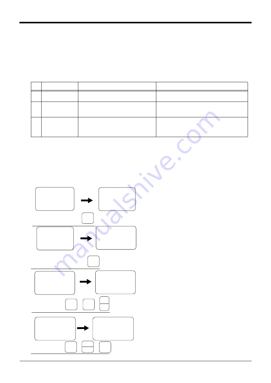
1
) Press the [5] key on the menu screen, and
1
) Press the [5] key on the menu screen, and
1
) Press the [5] key on the menu screen, and
1
) Press the [5] key on the menu screen, and
display the maintenance screen.
display the maintenance screen.
display the maintenance screen.
display the maintenance screen.
2) Press the [4] key on the maintenance screen,
2) Press the [4] key on the maintenance screen,
2) Press the [4] key on the maintenance screen,
2) Press the [4] key on the maintenance screen,
and display the origin setting method selection
and display the origin setting method selection
and display the origin setting method selection
and display the origin setting method selection
screen.
screen.
screen.
screen.
3) Press the [3] key and select the jig method.
3) Press the [3] key and select the jig method.
3) Press the [3] key and select the jig method.
3) Press the [3] key and select the jig method.
Then, press the [
1
] key and the [INP] key to
Then, press the [
1
] key and the [INP] key to
Then, press the [
1
] key and the [INP] key to
Then, press the [
1
] key and the [INP] key to
turn the servo OFF.
turn the servo OFF.
turn the servo OFF.
turn the servo OFF.
Securely fix the transportation jig A to the base
Securely fix the transportation jig A to the base
Securely fix the transportation jig A to the base
Securely fix the transportation jig A to the base
with the fixing bolts (M4
with the fixing bolts (M4
with the fixing bolts (M4
with the fixing bolts (M4 x
x
x
x
1
2, 2 bolts) in this
1
2, 2 bolts) in this
1
2, 2 bolts) in this
1
2, 2 bolts) in this
state.
state.
state.
state.
4) As for a release of the brake, set "
1
" to the axis
4) As for a release of the brake, set "
1
" to the axis
4) As for a release of the brake, set "
1
" to the axis
4) As for a release of the brake, set "
1
" to the axis
column of the "BRAKE" which the brakes are to
column of the "BRAKE" which the brakes are to
column of the "BRAKE" which the brakes are to
column of the "BRAKE" which the brakes are to
be released, and press the [+X] key while holding
be released, and press the [+X] key while holding
be released, and press the [+X] key while holding
be released, and press the [+X] key while holding
down the [MOVE] key. The brake of specified
down the [MOVE] key. The brake of specified
down the [MOVE] key. The brake of specified
down the [MOVE] key. The brake of specified
axis will be released only while the [+X] key is
axis will be released only while the [+X] key is
axis will be released only while the [+X] key is
axis will be released only while the [+X] key is
pressed.
pressed.
pressed.
pressed.
No
No
No
No
Method
Method
Method
Method
Explanation
Explanation
Explanation
Explanation
Remarks
Remarks
Remarks
Remarks
1
11
1
Origin data input
Origin data input
Origin data input
Origin data input
method
method
method
method
The origin data set as the default is input from
The origin data set as the default is input from
The origin data set as the default is input from
The origin data set as the default is input from
the T/B.
the T/B.
the T/B.
the T/B.
The setting method is explained in "2.3 Setting the origin" on
The setting method is explained in "2.3 Setting the origin" on
The setting method is explained in "2.3 Setting the origin" on
The setting method is explained in "2.3 Setting the origin" on
page
2
22
2
Jig method
Jig method
Jig method
Jig method
The transportation jig is installed, and the
The transportation jig is installed, and the
The transportation jig is installed, and the
The transportation jig is installed, and the
transportation posture is set as the origin
transportation posture is set as the origin
transportation posture is set as the origin
transportation posture is set as the origin
posture.
posture.
posture.
posture.
The setting method is explained in "5.5.
The setting method is explained in "5.5.
The setting method is explained in "5.5.
The setting method is explained in "5.5.
55.
55.
55.
55.
3
33
3
User origin method
User origin method
User origin method
User origin method
A randomly designated position is set as the
A randomly designated position is set as the
A randomly designated position is set as the
A randomly designated position is set as the
origin posture.
origin posture.
origin posture.
origin posture.
Before using this method, the origin must be set with the origin
Before using this method, the origin must be set with the origin
Before using this method, the origin must be set with the origin
Before using this method, the origin must be set with the origin
data input method (No.
1
above) or jig method (No. 2 above).
data input method (No.
1
above) or jig method (No. 2 above).
data input method (No.
1
above) or jig method (No. 2 above).
data input method (No.
1
above) or jig method (No. 2 above).
The setting method is explained in "5.5.2 User origin method" on
The setting method is explained in "5.5.2 User origin method" on
The setting method is explained in "5.5.2 User origin method" on
The setting method is explained in "5.5.2 User origin method" on
page 58.
<MENU>
<MENU>
<MENU>
<MENU>
1
.TEACH 2.RUN
1
.TEACH 2.RUN
1
.TEACH 2.RUN
1
.TEACH 2.RUN
3.FILE 4.MONI
3.FILE 4.MONI
3.FILE 4.MONI
3.FILE 4.MONI
5.MAINT 6.SET
5.MAINT 6.SET
5.MAINT 6.SET
5.MAINT 6.SET
<MAINT>
<MAINT>
<MAINT>
<MAINT>
1
.
1
.
1
.
1
.PARAM 2.INIT
PARAM 2.INIT
PARAM 2.INIT
PARAM 2.INIT
3.BRAKE 4.
3.BRAKE 4.
3.BRAKE 4.
3.BRAKE 4.ORIGIN
ORIGIN
ORIGIN
ORIGIN
5.POWER
5.POWER
5.POWER
5.POWER
Display the maintenance screen
Display the maintenance screen
Display the maintenance screen
Display the maintenance screen
+C
+C
+C
+C
(J6)
(J6)
(J6)
(J6)
5
5
5
5
STU
STU
STU
STU
<JIG>
<JIG>
<JIG>
<JIG>
SERVO OFF
SERVO OFF
SERVO OFF
SERVO OFF
OK ? (
1
)
OK ? (
1
)
OK ? (
1
)
OK ? (
1
)
1
:EXECUTE
1
:EXECUTE
1
:EXECUTE
1
:EXECUTE
Display the method selection screen
Display the method selection screen
Display the method selection screen
Display the method selection screen
<MAINT>
<MAINT>
<MAINT>
<MAINT>
1
.
1
.
1
.
1
.PARAM 2.INIT
PARAM 2.INIT
PARAM 2.INIT
PARAM 2.INIT
3.BRAKE 4.
3.BRAKE 4.
3.BRAKE 4.
3.BRAKE 4.ORIGIN
ORIGIN
ORIGIN
ORIGIN
5.POWER
5.POWER
5.POWER
5.POWER
<ORIGIN>
<ORIGIN>
<ORIGIN>
<ORIGIN>
1
.DATA 2.MECH
1
.DATA 2.MECH
1
.DATA 2.MECH
1
.DATA 2.MECH
3.JIG 4.ABS
3.JIG 4.ABS
3.JIG 4.ABS
3.JIG 4.ABS
5.USER
5.USER
5.USER
5.USER
-Y
-Y
-Y
-Y
(J2)
(J2)
(J2)
(J2)
4
44
4
MNO
MNO
MNO
MNO
<ORIGIN>
<ORIGIN>
<ORIGIN>
<ORIGIN>
1
.DATA 2.MECH
1
.DATA 2.MECH
1
.DATA 2.MECH
1
.DATA 2.MECH
3.JIG 4.ABS
3.JIG 4.ABS
3.JIG 4.ABS
3.JIG 4.ABS
5.USER
5.USER
5.USER
5.USER
Select the jig method
Select the jig method
Select the jig method
Select the jig method
-Z
-Z
-Z
-Z
(J3)
(J3)
(J3)
(J3)
3
33
3
JKL
JKL
JKL
JKL
→
→
→
→
-B
-B
-B
-B
(J5)
(J5)
(J5)
(J5)
1
11
1
DEF
DEF
DEF
DEF
→
→
→
→
INP
INP
INP
INP
EXE
EXE
EXE
EXE
Release the brakes
Release the brakes
Release the brakes
Release the brakes
<AXIS>
1
2345678
<AXIS>
1
2345678
<AXIS>
1
2345678
<AXIS>
1
2345678
BRAKE
BRAKE
BRAKE
BRAKE (00000000)
(00000000)
(00000000)
(00000000)
SET AXIS
SET AXIS
SET AXIS
SET AXIS (00000000)
(00000000)
(00000000)
(00000000)
ORIGIN :NOT DEF
ORIGIN :NOT DEF
ORIGIN :NOT DEF
ORIGIN :NOT DEF
STEP
STEP
STEP
STEP
MOVE
MOVE
MOVE
MOVE
+X
+X
+X
+X
(J
1
)
(J
1
)
(J
1
)
(J
1
)
.
.
.
.
ユ
;^
ユ
;^
ユ
;^
ユ
;^
+
+
+
+
-B
-B
-B
-B
(J5)
(J5)
(J5)
(J5)
1
11
1
DEF
DEF
DEF
DEF
→
→
→
→
<AXIS>
1
2345678
<AXIS>
1
2345678
<AXIS>
1
2345678
<AXIS>
1
2345678
BRAKE
BRAKE
BRAKE
BRAKE ((((
1111
1111
1111
1111
0000)
0000)
0000)
0000)
SET AXIS
SET AXIS
SET AXIS
SET AXIS (00000000)
(00000000)
(00000000)
(00000000)
ORIGIN :NOT DEF
ORIGIN :NOT DEF
ORIGIN :NOT DEF
ORIGIN :NOT DEF


