background image


32 


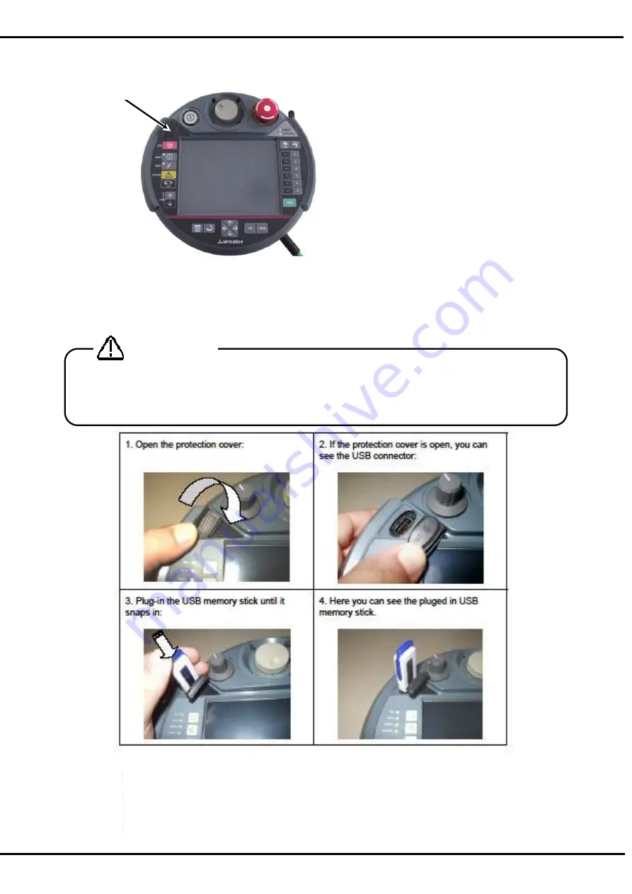
10.  USB memory stick 


Note) The operation method is the same although the photograph shown below differs from the actual 

product slightly. 


10.1.  Plug-in the USB memory stick 


The USB memory stick will be detected immediately and will be shown as Hard 
Disk. 

*

This picture is sample.


Never unplug the USB memory stick during accessing (read / write operations). It causes the 
failure. 
Please shut the cover surely after unplugging the USB memory stick. Otherwise the foreign body 
enters the connector, and it causes the malfunction. 

CAUTION


USB memory stick 

Содержание R56TB

Страница 1: ...Mitsubishi Industrial Robot CR750 CRn 700 Series R56TB R57TB Instruction Manual BFP A8684 F...

Страница 2: ...e following precautions and the separate Safety Manual before starting use of the robot to learn the required measures to be taken Safety Precautions CAUTION WARNING CAUTION WARNING CAUTION CAUTION CA...

Страница 3: ...utions given in the separate Safety Manual are given below Refer to the actual Safety Manual for details CAUTION CAUTION CAUTION CAUTION CAUTION CAUTION WARNING WARNING CAUTION WARNING CAUTION CAUTION...

Страница 4: ...8 CAUTION CAUTION WARNING...

Страница 5: ...05 10 BFP A8684 C Corresponds to the version 2 5 Add the Electric Hand function Add the Multi Hand function 2011 11 30 BFP A8684 D Corresponds to the version 3 0 Add the Operation Panel function Add...

Страница 6: ......

Страница 7: ...ism control 9 9 JOG operation 10 9 1 Speed setting 10 9 2 Jog mode 11 9 3 Switching Tool Data 12 9 4 Switching Base Coordinates 13 9 5 JOINT jog operation 14 9 6 XYZ jog operation 15 9 7 TOOL jog oper...

Страница 8: ...Function 67 11 3 3 Addition of position data for SQ Direct Function 68 11 3 4 Initialization of position data for SQ Direct Function 69 11 3 5 Confirming the position data for SQ Direct Function Posi...

Страница 9: ...7 16 1 1 Origin data input 118 16 1 2 The others Mechanical stopper TOOL ABS User origin method 119 16 2 Initialize 121 16 2 1 Setting the controller s date and time 121 16 2 2 Erase all programs in t...

Страница 10: ...9 4 Jog 160 17 4 9 5 Hand 161 17 4 9 6 Warm up 161 17 4 9 7 Start each slot 162 17 4 9 8 Stop each slot 162 17 4 9 9 Servo ON OFF each robot 163 17 4 9 10 Machine lock each robot 163 17 4 10 RS 232 16...

Страница 11: ...te system 203 19 1 5 9 Label 204 19 1 5 10 Save and end of editing user definition screen 205 19 1 6 Edit of existing parts 206 19 1 7 Copy movement of parts 207 19 1 8 Deletion of parts 208 19 1 9 Ch...

Страница 12: ......

Страница 13: ...this book the operation of the program edit etc is explained by the example of MELFA BASIC V program When using MELFA BASIC IV please read the command and line No in a different way and use this book...

Страница 14: ...talling and removing the T B The installation of T B is finished 2 2 Removing the T B Explain the removing method of T B below Check that the POWER power supply switch of the robot controller is OFF R...

Страница 15: ...to be operated with finger or stylus Note1 The following list gives an overview about the tested USB memory sticks and their manufacturers 1 Kingston Data Traveler Manufacturer Kingston Type USB 2 0...

Страница 16: ...canceled Moreover push this button when releasing the brake 12 HOME button Return the robot to the Home position that set beforehand This function is available with Ver 2 3 or later of this software...

Страница 17: ...rate the enable switch by finger and operate the screen and button by another hand Since the screen is the touch panel operate it with a touch stylus 4 2 Selection of items on touch panel After tap th...

Страница 18: ...e keyboard is displayed when the KEY h is tapped on each screen and the hoped character can be input Details are explained in the paragraph of the operation of each screen i is shown if you make the b...

Страница 19: ...Guidance screen is displayed for the basic setting such as the origin setting at the controller started for the first time There are three following functions in this screen 1 RC time setting 2 Robot...

Страница 20: ...e robot origin by input the origin data Tap the Edit button to input origin data The origin data to be input is noted in the origin data sheet enclosed with the arm or on the origin data history table...

Страница 21: ...function to control up to two excluding the standard robots robots user mechanism driven by servo motors besides the standard robots For more information please refer to the separate manual ADDITIONAL...

Страница 22: ...do the setup of speed LOW and HIGH are fixed dimension feed The STATUS NUMBER display of the controller is 3 Even if it continues pressing the button at the time of the fixed dimension feed the robot...

Страница 23: ...e is displayed in the combo box b Jog mode can be selected from this combo box Please refer to separate manual ROBOT ARM SETUP MAINTENANCE which provides more detailed explanations Note WORK jog mode...

Страница 24: ...roller connected TOOL0 MEXTL TOOL1 MEXTL1 TOOL2 MEXTL2 TOOL3 MEXTL3 TOOL4 MEXTL4 TOOL5 MEXTL5 TOOL16 MEXTL16 When the robot moves with changing tool data the tool data needs to be changed by setting t...

Страница 25: ...00 Ver S1 or later CR750 Q CRnQ 700 Ver R1 or later The content of the display is as follows Display Content BASE The state where base conversion data is directly specified by the program BASE0 The st...

Страница 26: ...taching the servo power supply can be turned off and can stop the robot The servo will turn ON when the SERVO button d pressed in the condition that the enable switch is pushed When the servo turns on...

Страница 27: ...ching the servo power supply can be turned off and can stop the robot The servo will turn ON when the SERVO button d pushed in the condition that the enable switch is pushed When the servo turns on LE...

Страница 28: ...aching the servo power supply can be turned off and can stop the robot The servo will turn ON when the SERVO button d pushed in the condition that the enable switch is pushed When the servo turns on L...

Страница 29: ...or detaching the servo power supply can be turned off and can stop the robot The servo will turn ON when the SERVO button d pushed in the condition that the enable switch is pushed When the servo turn...

Страница 30: ...detaching the servo power supply can be turned off and can stop the robot The servo will turn ON when the SERVO button d pushed in the condition that the enable switch is pushed When the servo turns...

Страница 31: ...s b continuing pushing the enable switch of T B c By pushing in the enable switch still more strongly during jog feeding or detaching the servo power supply can be turned off and can stop the robot Th...

Страница 32: ...res 1 Push the JOG button b of T B and display the JOG operation screen Select the jog mode And Set the operation speed to High or Low b a The operation speed of the robot might exceed 250mm s In the...

Страница 33: ...ode And the Wheel mark d is displayed If tapping other axis name the target axis changes into that axis Moreover if tapping axis name of current target again it is released 3 Turn the servo on and rot...

Страница 34: ...or later of this software Moreover the software version of the controller which can use this function is as follows Controller S W Ver of the controller CR750 D CRnD 700 Ver R3 or later CR750 Q CRnQ...

Страница 35: ...ct CAV a combo box ON OFF The collision avoidance function when Jog is operated can be turned ON OFF The collision avoidance function is available with Ver 3 0 or later of this software Moreover the s...

Страница 36: ...nues being pushed By pushing in the enable switch still more strongly during hand alignment or detaching the servo power supply can be turned off and can stop the robot In the condition that the enabl...

Страница 37: ...as the Electric Hand The Electric Hand operation screen and the Normal Hand operation screen can be switched by the button b in the hand operation lower right of the screen The Electric Hand operation...

Страница 38: ...of the controller CR750 D CRnD 700 Version S2a or later CR750 Q CRnQ 700 Version R2a or later The electric hand table method can be used this software Version 3 1 or later And the software version of...

Страница 39: ...de is switched And a comment corresponding to the selected table or point is displayed i The condition of operating the Electric Hand is as follows Table 9 2 The condition of operating the Electric Ha...

Страница 40: ...he Speed Force and Point Origin The moving to the origin point is executed Only while holding down the button The same operation as time when the EHOrg instruction was executed is done Hand Servo Off...

Страница 41: ...pleted Busy Operating Stopping InPos Reached to the target position Unreached to the target position Hold Holding the works Not holding the works Zone The hand is in the zone specified by EHOpen instr...

Страница 42: ...tton c corresponding to the hand number is pushed the correspondence hand will open and if the button c is pushed it will close The state of hand I O signal is displayed from Ver 2 3 or later of this...

Страница 43: ...ted robot When the multi mechanism control is used select the model of the operated robot by the combobox of the model selection in the upper part of the screen If the multi mechanism control is not u...

Страница 44: ...k The USB memory stick will be detected immediately and will be shown as Hard Disk This picture is sample Never unplug the USB memory stick during accessing read write operations It causes the failure...

Страница 45: ...ample Never unplug the USB memory stick during accessing read write operations It causes the failure Please shut the cover surely after unplugging the USB memory stick Otherwise the foreign body enter...

Страница 46: ...gram button b is tapped and a program list is displayed At this time if it creates newly to a robot controller the Robot radio button c is checked If it creates newly to a USB memory the USB radio but...

Страница 47: ...SB memory The functions which can be executed also differ The edit screens include the command editing screen and the position editing screen The command editing screen will be displayed first If the...

Страница 48: ...and display menu panel 2 Program button b is tapped and a program list is displayed At this time if it creates newly to a robot controller the Robot radio button c is checked If it creates newly to a...

Страница 49: ...he command edit screen is displayed The buttons displayed differ by the case where the edit screen targets the robot controller and the case where the edit screen targets the USB memory The functions...

Страница 50: ...tes it will return to the program list c The buttons displayed differ by the case where the edit screen targets the robot controller and the case where the edit screen targets the USB memory The funct...

Страница 51: ...ve if the sandglass is displayed and it completes it will return to the original edit screen The buttons displayed differ by the case where the edit screen targets the robot controller and the case wh...

Страница 52: ...turns to the edit screen Cancel Tap each button The buttons displayed differ by the case where the edit screen targets the robot controller and the case where the edit screen targets the USB memory Th...

Страница 53: ...right side of the character mistaken by the cursor key of and d and tap the Back Space key If the Clear key e of the keyboard is tapped package erasure can be carried out and the inputted character c...

Страница 54: ...es can be selected a 2 Tap the Delete button b the selected line of code or the position variable will be deleted It becomes the error when it is going to delete the position variable currently used b...

Страница 55: ...istaken operation the operation done last time will return If 3 Mov J1 has been deleted incorrectly 3 Mov J1 is return Only last one operation is valid to undo All cannot be returned if two or more op...

Страница 56: ...ct the line to cut or copy Two or more lines can be selected a 2 Tap the Menu button of the command edit screen and if it move tap the Cut Line b or if it copies tap the Copy 3 Select just before the...

Страница 57: ...hich confirms the line number and the line interval at the copy destination is displayed Please change the line number if necessary in the keyboard screen displayed by tapping edit key b Please set th...

Страница 58: ...ing row number does not exist the existing line of code and the new line of code will be mixed Please check securely the new row number when pasting and the line pitch Especially if pasting two or mor...

Страница 59: ...renumbered Checks the radio button of Range designation b if the line of the specification range is renumbered And specify the target range by the start row number inputted into Start line also the en...

Страница 60: ...the message that the row number after the renumber has already existed In this case the renumber is not executed Tap the OK button i h i Even if row number not existing is specified to the range it e...

Страница 61: ...of the command edit screen 2 Input start Line number into Start line and Line pitch into Line pitch Inputs from the keyboard which taps the Edit button b and is displayed 3 Preparation will be complet...

Страница 62: ...setting screen will be displayed The line of code selected beforehand is inputted into Find what as a specification character string 2 The input of the character string to search taps the Edit button...

Страница 63: ...fied with checking Up Down g Display the message if the character string is not found Taps the OK button h 4 Tap the Close button i to finish f g h i The row number is also the target of search If it...

Страница 64: ...le by the Up Down key d of the keyboard Tap the Enter key e of the keyboard to finish the input 3 If each button of the replacement character string specified screen is tapped it will operate as follo...

Страница 65: ...nly last one operation is valid to undo All cannot be returned if two or more operations have been mistaken In this case it is necessary to finish program edit without saving and to do over edit from...

Страница 66: ...on 1 Tap the Jump button a of the command edit screen The setting screen will be displayed 2 To input the label or line number tap the Edit button b and uses the keyboard that displayed Tap the Enter...

Страница 67: ...55 If the specified row number does not exist jump to the near place Display the error message if the specified label does not exist Tap the OK button e close the error message window and try again e...

Страница 68: ...ble Joint Global Joint type variable System variable 11 2 1 Registering the current position data The procedure of registering the robot s current position is shown 1 By jog operation move the robot t...

Страница 69: ...57 3 If the Get current position button c of the data edit screen is pushed will take in the robot s current coordinate value 4 Tap the OK button d and register the data c d...

Страница 70: ...l value is shown 1 Select the variable of editing and tap the Edit button a The data edit screen is displayed 2 Tap the Edit value button b The data input screen is displayed 3 The data is inputted in...

Страница 71: ...the Edit FLG1 button d The multi rotation flag can be edited by the Edit FLG2 button e Tap the OK button f will fix the data 5 The OK button g will be tapped if edit of all the data is completed The p...

Страница 72: ...ariable name from the keyboard displayed and tap the Enter button c to fix it 3 Input the each coordinate value the structure flag and multi rotation data One method is taking the current position of...

Страница 73: ...le currently used by the command line cannot be deleted Select the variable of deleting and tap the Delete button a The selected position variable is deleted The position variable currently used by th...

Страница 74: ...ill turn ON when the SERVO button b pushed in the condition that the enable switch c is pushed When the servo turns on LED green of the SERVO button lights up 4 Only while the enable switch is pushed...

Страница 75: ...sition data is shown 1 Tap the Find button a The variable name input screen is displayed 2 Tap the Edit button b The string input screen is displayed 3 The variable name to find is inputted tap the En...

Страница 76: ...ion type variable And the position No is special 1 to 999 and 999 points are always prepared These variables are treated as external variable P_DM 1 to P_DM 999 in the controller Moreover the name of...

Страница 77: ...65 In the SQ Direct Function the position data that can be used is only the Position type variable CAUTION a...

Страница 78: ...o the controller When you want to teach after confirming the current position data tap the Edit button c and display the data edit screen d 3 When the Get current position button e of the data edit sc...

Страница 79: ...yed e 3 The data is inputted into each coordinate value tap the OK key f and finish the data input 4 The structure flag can be edited by the Edit FLG1 button g The multi rotation flag can be edited by...

Страница 80: ...keyboard d displayed and tap the OK key e to fix it 3 Input the each coordinate value the structure flag and multi rotation data One method is taking the current position of robot And another method i...

Страница 81: ...efer to 11 2 5 Confirming the position data Position jump for detail operation 11 3 6 Saving the position data for SQ Direct Function to USB Position data for SQ Direct Function cannot be saved to the...

Страница 82: ...py screen will appear The position data for SQ Direct Function needs to change its file name to copy Tap the Edit button and input the saved file name e Tap the OK button f the position data for SQ Di...

Страница 83: ...files of position data for SQ Direct Function can be displayed 2 Confirm that the file of position data for SQ Direct Function in USB memory is selected in the Source list select the Robot d as the d...

Страница 84: ...USB memory is overwritten Do not write protect the USB memory when you do the operation as write to it Even if it seems to have been able to write it without the error occurring by the operation copy...

Страница 85: ...ram runs without error 12 1 Starting the step operation The Debugging window is shown from the Edit command window editing in the robot controller or the Program monitor window Tap the Debug button a...

Страница 86: ...set the error turn the servo ON and start step operation Release or forcibly push the enable switch The servo will turn OFF and the moving robot will immediately stop Error 2000 will occur To resume o...

Страница 87: ...oreover push the sheet key key and the executing line of the program that has been selected now can be put backward by one line The skip function is available even if the Enable switch is not pushed o...

Страница 88: ...ackward for the selected slot 12 2 6 Step jump It is possible to change the start line 1 Push the sheet key key corresponding to the JUMP the Line window will appear 2 Set the line number and tap the...

Страница 89: ...pping the breakpoint is automatically deleted at the same time as stopping 1 Set a Breakpoint The breakpoint is set according to the following procedure 1 Select the command line where breakpoint is s...

Страница 90: ...s the file which position data for SQ Direct Function is saved The position data for SQ Direct Function can be edited operated by operating the file SQ Direct The targets of any operations in this fun...

Страница 91: ...f operation Function In the controller In the USB memory New x x Open o o Delete x o Protect x x Rename x o Compare o o Select x x Function Proprieties Remarks Controller Controller x Controller USB o...

Страница 92: ...tion time No of cycles and Comment are displayed As for the program files in the USB memory and in the controller when even the contents are the same the program sizes are different Select USB and tap...

Страница 93: ...list and designate the destination robot or folder in the USB memory at the Destination to copy to The multiple program files can be selected at the same time but for copying with changing its name on...

Страница 94: ...older in the USB memory at the Destination to move to The multiple program files can be selected at the same time 2 Tap the Move button a 13 5 Delete The program files can be deleted 1 Select the prog...

Страница 95: ...le program files can be selected at the same time 2 Tap the Protect button on Program list window and Setting for protect window will appear 3 Set the condition of the protect and tap the OK button a...

Страница 96: ...re button on Program list window and Compare window will appear 1 Select the program files to be compared from the left and right lists 2 Tap the Compare button a and Setting for compare window will a...

Страница 97: ...different as follows Since Ver 2 3 it is changed to judge the same position variable when the value of each element of a position variable is coincides No Example of variable of object of comparison 1...

Страница 98: ...el is installed on the controller set the controller MODE switch to AUTOMATIC 2 Make the T B enable Push the TEACH switch of T B and confirm that the TEACH switch and the TB ENABLE lamps light 3 Selec...

Страница 99: ...ntroller 14 1 Starting Select Backup Restore from the menu The following Backup Restore window appears Precautions when executing a backup restore operation during the replacement of a controller CPU...

Страница 100: ...using the program editing tool Parameter List Files This is used to edit the parameter information saved by backup in offline mode of RT ToolBox and is not required for backup If this is not checked t...

Страница 101: ...ransferred If not checked Loads the origin information from the robot controller transfers the information in the designated folder and then returns the origin information that has been loaded to the...

Страница 102: ...origin data may have been changed Precaution for Restore When a program is running or the ALWAYS program is set up If a batch restoration or a program restoration is executed when the program is bein...

Страница 103: ...er again If connecting to the CRnD 700 series controller the power reset of the robot controller can be performed from the T B If connecting to the CRnQ 700 series controller please reset the power by...

Страница 104: ...he currently connected robot controller can be constantly displayed 15 1 Starting Select the Monitor from the Menu The Monitor menu shown below will appear After selecting the robot you wan to monitor...

Страница 105: ...med General purpose signal The state of the signal input from an external device to the robot controller output from the robot controller to an external device can be confirmed Named signal The status...

Страница 106: ...he slots in the robot controller can be monitored The No of displayed slots is determined with the parameters It is possible to stop all slots for which the start condition is ALWAYS by tapping Stop A...

Страница 107: ...unning program can be monitored 1 Program monitor Watch The constant display window for the variables used in the running program is displayed Debug The Debugging window will appear at the right of T...

Страница 108: ...variable list used by the program When Select value button b is tapped the following screen is displayed Add button e is tapped after the variable watched on this screen is selected and the variable m...

Страница 109: ...button d is tapped while selected Variable value change window is displayed Please note that the movement of the robot might change by the change enough when you change the value CAUTION When the var...

Страница 110: ...the following for the variable which can be displayed by the hexadecimal number Integer The displayed variable can be switched to the hexadecimal number the decimal number Float When it is 0 below th...

Страница 111: ...played 1 Currently occurring errors The history of the errors that have occurred in the past can be referred to Detailed information cause and recovery of the occurring error can be confirmed The Erro...

Страница 112: ...Error history The history of errors that have occurred in the past can be referred to This display is not shown at all times Detailed information can be confirmed Error history is preserved in the tex...

Страница 113: ...the input output signals can be monitored When the Pseudo input button is tapped on the robot controller will enter the pseudo input mode and the following window will appear To cancel the pseudo inpu...

Страница 114: ...controller general purpose input signals Tap on the Pseudo input button a i First the signal to be pseudo input signal is read 16 signals can be set simultaneously Input the head No of the signal to...

Страница 115: ...te of the 16 signals is displayed with the designated signal at the head Set the output state and then tap on the Bit Forced Output button f iii 16 signals from the No designated as the head can be fo...

Страница 116: ...of the signals you want to monitor in the Start and End boxes and name it If the signal you want to monitor is one bit enter only the start No For multiple bits enter the numbers so that the start No...

Страница 117: ...utton If the save destination is a personal computer a file name can be specified However if the save destination is a robot controller the result will be overwritten on the previous information The f...

Страница 118: ...only No 6000 is possible The input registers are pseudo input The output registers are forcibly output 1 Monitor setting The register to be monitored can be changed Please tap the Monitor setting but...

Страница 119: ...signated number of registers will appear with the designated register at the head iii Set the register value and tap on the INPUT button e The pseudo input mode is canceled when this window is closed...

Страница 120: ...r the hexadecimal number The signals to display can set up the continuous range freely with Monitor setting This function can be used with Version R3 or later of CR750 Q CRnQ 700 robot controllers and...

Страница 121: ...med The connected robot and it s servo ON time can be confirmed 15 3 3 2 Production information The latest cycle operation time No of cycles and average cycle time for each program in the robot contro...

Страница 122: ...al board information Information on the option card mounted on the robot controller can be confirmed Note that this screen cannot be referred to if robot controller is not provided with a slot for mou...

Страница 123: ...sition in one rotation of the encoder is displayed It is not displayed in the CR750 700 series controller It always becomes 0 Fdt command The amount of the change of the position command between the c...

Страница 124: ...ck A present motor speed is displayed by the unit of rpm Speed MAX The maximum value of the speed feedback after robot controller s power supply is turned on is displayed When the Reset button on the...

Страница 125: ...mmand after robot controller s power supply is turned on is displayed When the Reset button on the screen is tapped this value is reset in 0 Max current cmd2 The maximum value of the current command f...

Страница 126: ...114 Current2 a...

Страница 127: ...axis load level The maximum value of the axis load level after robot controller s power supply is turned on is displayed When the Reset button on the screen is tapped this value is reset in 0 Encoder...

Страница 128: ...power voltage in servo ON is displayed When the Reset button on the screen is tapped this value is reset in 0 Motor power voltage MIN The minimum value of the motor power voltage in servo ON is displa...

Страница 129: ...s set so that the robot can be used with a high accuracy After purchasing the robot always carry out this step before starting work The origin must be reset if the combination of robot and controller...

Страница 130: ...to the back side of the robot arm cover DJNT value is used by the position repair tool in RT ToolBox 1 Edit origin data If origin data is changed tap Edit button a and shown the following window 2 Wr...

Страница 131: ...the origin data in the designated file is loaded 16 1 2 The others Mechanical stopper TOOL ABS User origin method These origins set way is shown almost the same screen and do the same operation In th...

Страница 132: ...u need move axis with brake by the hand please release the break and work by two people Tap Release the brakes button a the Release the brakes screen is displayed See chapter 16 4 Releasing the brakes...

Страница 133: ...g the controller s date and time 2 Erase all programs in the controller 3 Initialize the battery remaining time 4 Set a serial number 16 2 1 Setting the controller s date and time Tap the Set time but...

Страница 134: ...reen All programs in the robot controller are deleted by operating the above mentioned 16 2 3 Initialize the battery remaining time To initialize the battery remaining time follow the procedure below...

Страница 135: ...serial number of the robot arm is set Each mechanism can be set The serial number of the robot arm has been put on the back of the body of the robot base 16 3 1 Serial Number setting 1 Tap on Set butt...

Страница 136: ...Input the serial number from the displayed keyboard After the serial number is input tap on Enter key of the keyboard 3 Tap on Write button to write into the controller After writing last updated date...

Страница 137: ...a specified file Save serial number to file ends above 16 3 3 Write serial number in a file to the controller 1 Tap on Read from file button of the serial number setting 2 When Open button is tapped...

Страница 138: ...ove the robot arm by hand etc Due to the robot configuration when the brakes are released the robot arm will drop with its own weight depending on the released axis Always assign an operator other tha...

Страница 139: ...Before releasing the brakes it is necessary to do the following operation 1 The MODE switch is set to MANUAL 2 TEACH button is set to ON 3 Push the enable switch 4 Press the CAUTION button Another per...

Страница 140: ...on is being pressed 16 4 3 Releasing the brakes of two of more axes For releasing the brakes of two or more axes do following operation after doing 1 operation 1 Select axes to release the brakes 2 Pr...

Страница 141: ...tenance menu The Maintenance Forecast window appears Maintenace menu Maintenance Forecast 16 5 2 Forecast Battery When the information for Maintenance Forecast has been loaded from the controller the...

Страница 142: ...time on the Setup screen x Operation time of a day the hours and bar graphs are displayed in orange The display unit setting can be switched between time and day If day is selected in the display unit...

Страница 143: ...ime on the Setup screen x Operation time of a day the hours and bar graphs are displayed in orange The display unit setting can be switched between time and day If day is selected in the display unit...

Страница 144: ...the controller again For more information about the setup items see Tab Setup Screen Information needed to Maintenance Forecast is not accumulated while the Maintenance forecast is being invalidly set...

Страница 145: ...OFF 6 Assumption operation time of a day Enter an estimated robot operation hours per day 16 hours 7 The remainder days until presumed maintenance time Specify the number of days remaining until presu...

Страница 146: ...C7510 or C7520 occurs and the batteries have been replaced Be sure to reset the battery remaining time after a battery has been replaced At the time of grease replenishment When an alarm urging to pe...

Страница 147: ...he controller CPU is replaced perform both backup and restore operations in a batch using the Backup Restore tool Also be sure to back up the information for Maintenance Forecast before replacement an...

Страница 148: ...ting to set the origin data to during start the controller first time is displayed In this screen the following three functions are provided For more information please refer to the 7 Guidance 1 RC ti...

Страница 149: ...grams Reading the programs Copying the programs Renaming the programs Deleting the programs Writing the position data for SQ Direct Reading the position data for SQ Direct Program Deletion of all robo...

Страница 150: ...ters or less The character that can be used is as follows Tabl Character that can be used by password Character that can be used by password 8 characters or more and 32 characters or less Number from...

Страница 151: ...button of the item to which change the password in Password Setup screen After inputting a password set now and a new password in the Register Change Password screen tap OK button Figure Change Passw...

Страница 152: ...the Delete button of the item to which delete the password in Password Setup screen After inputting a password set now in the Delete Password screen tap OK button Figure Delete Password When the passw...

Страница 153: ...odels and robot controller versions with which the Tool automatic calculation can be used are as follows Table 16 1 Supported Robot Controllers and Models No Robot model CR750 700 series Robot Control...

Страница 154: ...e tool number for setting a Select the line of Auxiliary point b Teach selection line c Enter checks to the check box of the line used to calculation b After teaching the check box is updated Re teach...

Страница 155: ...fer to 11 2 5 Confirming the position data Position jump When a value is set to Calculated tool coordinate a Write button f becomes effective When the Write button f is tapped the values of a tool par...

Страница 156: ...ter editor The parameter editor can be used to reference and rewrite the parameter information set in the robot controller 17 1 Starting Select the Parameter from the menu and parameter editor shown b...

Страница 157: ...t controller or when the Read button a is tapped on Parameter window of T B 2 When there is no parameter list information in the T B 3 When the parameter list used in the robot controller is newer tha...

Страница 158: ...ower case alphabetic characters can be used in this parameter setting Use upper case letters when naming the programs in alphabetic characters for the parameters of the base program PRGUSR or slot tab...

Страница 159: ...with Ver 2 3 or later of this software I O unit and Force control are available with Ver 3 0 or later of this software Moreover there is a restriction of the software version of the controller which c...

Страница 160: ...8 17 4 1 Motion limit Set the operating range of the robot 17 4 2 JOG Set the speeds of joint jog and XYZ jog Override specifies maximum speed Maximum speed can be suppressed by reducing the value Mem...

Страница 161: ...ftware 17 4 3 4 Electric hand table can be used with Version 3 1 or later of this software 17 4 3 1 Hand Set the type of the hand single solenoid double solenoid etc and work holding non holding when...

Страница 162: ...Robot Remote Input Output Parallel Input Output Notes RV 2SQ 2SD series Not use RV 3SQ 3SD series 5 axis robot cannot use this parameter RV 6SQ 6SD series RV 12SQ 12SD series Not use By using the sta...

Страница 163: ...splayed in the parameter menu Please refer to Table 17 1 Robot that can use the Multi Hand Tool Table 17 2 Robot controller that can use the Multi Hand Tool for the controller and the robot which can...

Страница 164: ...e controller CR750 D CRnD 700 Ver S3e or later CR750 Q CRnQ 700 Ver R3e or later When the Set button is tapped after selecting the target electric hand and table list the Electric hand table setting s...

Страница 165: ...list Electric hand teach setting screen is displayed Tap the OK button after setting up the value of a position and comment on this screen The Electric hand teach screen is updated The controller whic...

Страница 166: ...available from this software Ver 2 5 or later And please refer to Table 17 4 Robot controller which can set the parameters about the electric hand for the controller which can set the parameters about...

Страница 167: ...e to set according to the kind of the connected robot In that case the row of WRKDAT0 cannot be input 17 4 5 Weight and size Hand Set the hand conditions HNDDAT0 might not be able to set according to...

Страница 168: ...s software corresponds to the Multi Hand it is possible to select Tool 5 or later This function is available from this software Ver 2 5 or later The Multi Hand function is available with the robot con...

Страница 169: ...h task slot during multi task operation Select the task slot number you are changing and tap the Set button a When the modification window appears set the program name operating conditions startup con...

Страница 170: ...RESET Set a signal number and then select one from OFF ON Hold The value of the signal having the specified number displayed in the list changes Also selecting a signal group for example 0 31 and then...

Страница 171: ...gnment Assign signal numbers to functions in order to perform the remote operations to execute and stop robot programs and display operate the execution progress information and servo power supply sta...

Страница 172: ...arameter is available with Ver 2 4 or later of this software Moreover the software version of the controller which can use this parameter is as follows Controller S W Ver of the controller CR750 D CRn...

Страница 173: ...161 17 4 9 5 Hand 17 4 9 6 Warm up...

Страница 174: ...162 17 4 9 7 Start each slot 17 4 9 8 Stop each slot...

Страница 175: ...163 17 4 9 9 Servo ON OFF each robot 17 4 9 10 Machine lock each robot...

Страница 176: ...p the communication environment of the RS 232C interface located at the front of the robot controller Only CRnD 750 Controller 17 4 11 User defined area Specify the area rectangular defined by two Car...

Страница 177: ...165 17 4 12 Free plane limit Set the overrun limit used on free planes 17 4 13 Home position Set the position of the escape point...

Страница 178: ...irm whether the commands can be used CAUTION 17 4 15 Robot additional axis You can set information related to addition axes of robots This function can be used with Version 3 2 or later of this softwa...

Страница 179: ...167...

Страница 180: ...he robot s collision detection functions This function can be used with Version 3 2 or later of this software 17 4 17 Warm up operation You can set information related to the robot s warm up function...

Страница 181: ...2 or later of this software The controller version which can use this function is as follows CR750 700 series CRn 500 series Maximum acceleration deceleration correction ratio J2 or later Compliance e...

Страница 182: ...ftware Double tap the error number from the list or tap Set button The User Error edit screen is displayed Input the error number error message cause and recovery method then tap the OK button The use...

Страница 183: ...e tap A screen is displayed for setting a variety of device information If you select MELFA 3D Vision or Network Vision Sensor 2D at Auto configuration the default value corresponding to each device i...

Страница 184: ...set when you are connected to CR750 Q CRnQ 700 series robot controller This function can be used with Version 3 2 or later of this software You can check the number of points input and range of total...

Страница 185: ...roller Also this function cannot be used with CRnQ 700 series robot controller If you use CRnQ 700 series robot controller please set it with the software of the PLC CAUTION You can reset the error of...

Страница 186: ...roller Also this function cannot be used with CRnQ 700 series robot controller If you use CRnQ 700 series robot controller please set it with the software of the PLC CAUTION You can reset the error of...

Страница 187: ...an use this parameter is as follows Controller S W Ver of the controller CR750 D CRnD 700 CR750 Q CRnQ 700 Ver R3 or later When a unit number in Unit is specified the parameter of the specified unit n...

Страница 188: ...he WORK jog function is available with Ver 2 3 or later of this software Moreover the software version of the controller which can use this function is as follows Controller S W Ver of the controller...

Страница 189: ...of the force control function Controller S W Ver of the controller CR750 D CRnD 700 Ver S3 or later CR750 Q CRnQ 700 Ver R3 or later 17 4 27 1 Force sensor Set the parameters Assign sensors Sensor coo...

Страница 190: ...ics Set the parameters Gain Instruction and Detection which are used by the control feature of force control function The Mode switch judgment Speed reference button is displayed in this software 3 1...

Страница 191: ...the parameters in the robot controller by tapping the Write button 17 4 27 4 Force log Set the parameters Configuration and FTP setting which are used by the force control function After you change th...

Страница 192: ...180 17 4 28 Real time external control command Set the information of the Real time external control MXT This function can be used with Version 3 2 or later of this software...

Страница 193: ...mxx TXT xx 01 to 10 It is possible to create the different definition files up to 10 Folder in T B to copy to IPSM MELFA UserDef Please make the UserDef folder by yourself Format of the parameter defi...

Страница 194: ...n the parameter list to the direction specified 17 6 Power Reset of the Robot Controller To make modified parameters effective it is necessary to power on the robot controller again The power reset of...

Страница 195: ...Display On Display set the screen name when T B is started and T B brightness The operation is as follows 1 Set the screen name when T B is started to Top screen 2 Set T B brightness to Brightness 3 T...

Страница 196: ...button You can update the T B software Download the update data compressed file Copy the files which are decompressed of update data to root folder of the USB memory ex If USB memory s drive letter i...

Страница 197: ...can see the screen as follows Check the versions before and after update and cautions and tap Start button start update Please do not turn off the controller during update If do that the T B may be br...

Страница 198: ...B Tap Setting button a After you tap Setting button a you can see the screen as follows You can set IP address Subnet Mask and Default gateway If the T B connect to the CRnQ controller set the IP add...

Страница 199: ...nition screen are as follows List 19 1 List of parts Parts Explanation 1 Button The signal can be output from the robot controller by tapping the button The signal can be output only in T B Enabling s...

Страница 200: ...B screen and display menu panel 2 Tap the Option button b in the menu The System option is displayed 3 You can edit by User definition screen c of System option window Please refer to List 19 2 Explan...

Страница 201: ...reen that has been selected is moved to above 7 User definition screen that has been selected is moved to below 8 Import User definition screen preserved in USB memory is imported 9 Export Selected Us...

Страница 202: ...on screen tap Edit button a on the window after selecting the user definition screen edited from the list The edit display of selected User definition screen is displayed Please refer to 19 1 5 Page e...

Страница 203: ...er definition screen is made c The name of the copied user definition screen becomes Origin Name copy 19 1 4 Deletion of page To delete the existing User definition screen tap Delete button b after se...

Страница 204: ...e registered with the block unit b delimited in this grid line 1 Name Page name is set The name can be input by Edit button 2 Line The ruled line is drawn on User definition screen 3 Save The content...

Страница 205: ...d 5 After the setting is completed tap OK button e 1 Name The name of the button is set The button name can be input by Button name edit button The button name can be displayed by two lines by checki...

Страница 206: ...ation settings operate individually by using each condition Moreover when High and Low are set to output to the same signal and both conditions become true the Condition2 is given priority If the oper...

Страница 207: ...nal g and select High Now select Input signal 4 Select High as signal operation of when tapping on a button h 5 The input area of output signal number is displayed Tap Signal No button j and input 20...

Страница 208: ...ighting condition and the turning off condition tap OK button f The set content is displayed d in the right of the On Off condition button 5 After setting the lamp color and lighting condition and the...

Страница 209: ...is Low 1 A default value of The Lamp on off condition window is shown in a right picture 2 Set On condition Tap h and Select the signal type Now select input signal 3 Tap Signal No button j and set 20...

Страница 210: ...ot Select task slot number for which the variable is used The range of slot number that can be set is different according to the system that uses it 3 Name Set the variable name Robot Status Variable...

Страница 211: ...ot information button b 3 Select Exe line c as the type on Create robot information window 4 After setting the information on the content of the program tap OK button d 1 Size Set the width of box in...

Страница 212: ...4 After setting the information of program name tap OK button d 1 Size Set the width of box in which program name is displayed The value from 1 to 16 can be set 2 Slot Select task slot number for whi...

Страница 213: ...ndow 4 After setting the information of execution line number tap OK button d 1 Size Set the width of box in which execution line number is displayed The value from 1 to 16 can be set 2 Slot Select ta...

Страница 214: ...3 Select Cur pos c as the type on Create robot information window 4 After setting the information of the current position data the XYZ coordinate system tap OK button d 1 Size Set the width of box in...

Страница 215: ...lect Cur jnt c as the type on Create robot information window 4 After setting the information of the current position data the joint coordinate system tap OK button d 1 Size Set the width of box in wh...

Страница 216: ...Tap the position block in which the label is made a The label is arranged in this position 2 After Select item window is displayed tap Label button b 3 After setting the label on Create label window...

Страница 217: ...205 19 1 5 10 Save and end of editing user definition screen After the editing of user definition screen is completed tap Save button a To end the edit tap Close button b a b...

Страница 218: ...parts Edit of existing parts is as follows 1 Tap a part which is edited a 2 After Edit menu window is displayed Tap Edit button b 3 The edit displays of selected parts are displayed After changing con...

Страница 219: ...t menu window is displayed tap Copy button b When parts are moved tap Move button 3 Tap the position block where the part is copied onto moved to At this time the current position block of part is red...

Страница 220: ...2 After Edit menu window is displayed tap Delete button b 3 Tap Yes button on the confirmation message 19 1 9 Change of page name Page name can be changed in Edit button a under the left of the window...

Страница 221: ...ed line is displayed in the right of Line button These buttons to draw the ruled line disappear when Line button c is tapped again 3 Select the kind of ruled line d Only one kind of the ruled line can...

Страница 222: ...utton These buttons to draw the ruled line disappear when Line button c is tapped again 3 Select the kind of ruled line d Only one kind of the ruled line can be selected 4 Tap the block e where the ru...

Страница 223: ...Install the USB memory 2 Tap Import button a 3 Select the import file in USB memory on Open window and tap open button 4 The selected user definition screen is added to the list If the user definition...

Страница 224: ...Enable by tapping this parts and displaying the input value screen Only at T B state is enabling 2 Page name The name of the user definition screen is displayed 3 4 The page is switched a b 2 3 4 1 No...

Страница 225: ...g if there are 15 information items to update and 10 items can be dealt by every 0 5 seconds While getting robot information the signal is not outputted by tap or tap the button 1 The signal output by...

Страница 226: ...isplayed with the software before version 3 0 Moreover the software version of the controller which can use this function is as follows Controller S W Ver of the controller CR750 D CRnD 700 Ver S3 or...

Страница 227: ...s being generated as a controller Cycle Stop The controller is cycle stop a b c d e When using it in the MANUAL mode Push the TEACH button Change to the enabling state Press this switch lightly when c...

Страница 228: ...e confirmation screen is displayed the Yes button e is tapped Note The program selection cannot be done while executing the program 20 4 Override UP DOWN Override is lowered with DOWN button a and it...

Страница 229: ...tton a the Caution dialog b is displayed An automatic driving begins when OK button c is tapped after safety is confirmed 20 7 Stop Tap the Stop button a the running program is immediately stopped and...

Страница 230: ...button a the confirmation message box b is displayed Tap the Yes button c the program is reset 20 9 Cycle stop If the Cycle Stop button a is tapped during the continuous operation the program will sto...

Страница 231: ...DEC 2013 MEE BFP A8684 Printed in Japan on recycled paper Specifications are subject to change without notice 8...

Отзывы: