3Installing the option devices
Installing the solenoid valve set
3-45
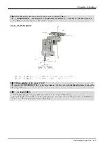
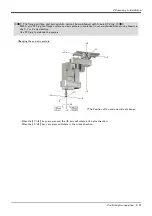
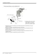
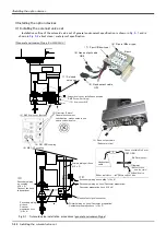
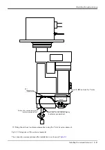
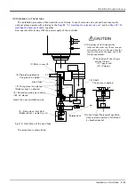
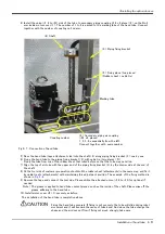
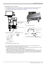
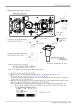
Fig.3-2 : Solenoid valve installation procedures (clean/ waterproof type)
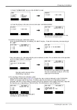
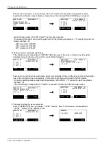
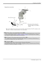
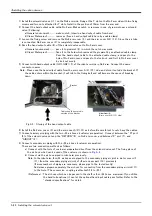
The installation procedures are as follow. This work must be carried out with the controller power turned OFF.
(オプションのハンド
チューブを接続)
ハンド出力ケーブル(GR1、GR2)
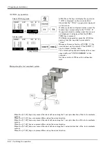
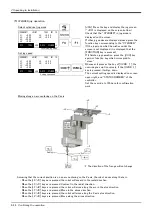
<3> No2 Arm cover (bottom)
<1> Solenoid
valve set
<8> RETURN coupling
<9> AIR OUT coupling
<2> Grommet (3 place)
Clean/ Waterproof specification :
removes in one near a solenoid
valve.
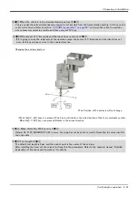
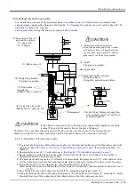
<11>
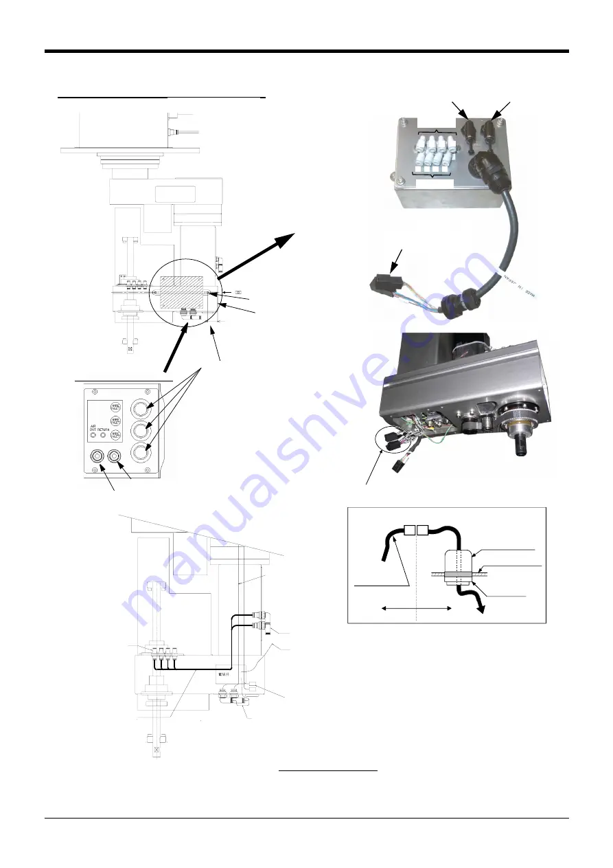
Secondary piping air coupling (φ4 x 4)
Secondary piping air hose (Customer preparation)
Customer preparation hose (φ4 x 4)
Hand output signal connector
Secondary piping
air coupling
(φ4 x 4)
Connect the hand
tube optional.
Secondary piping
air hose
Customer
preparation hose
(φ4 x 4)
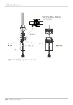
Primary piping air hose (Customer preparation)
Customer preparation hose (φ6 x 2)
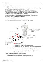
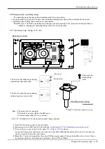
10mm
Solenoid valve set installation position
2-M5 Screw (for fixing)
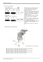
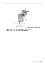
<13> Arm coverA(2)
<Clean/ Waterproof type
(RH-3SDHR3512C/3512W)
>
1
2
3
4
5
6
7
8
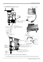
<7> P port
<6> R port
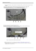
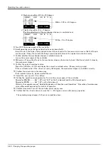
<4> Hand output cable
GR1,GR2
A port
B port
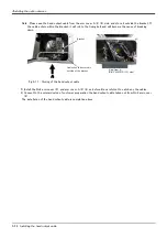
ロックナット
No.2アームカバー
ハンド出力
ケーブル
電磁弁へ
No.2アーム内で接続
(GR1,GR2)
ケーブルクランプ
電磁弁セット側
ロボット本体側
<10>
<5> Hand output cable
(Robot arm side)
Primary piping air hose
(φ6 x 2)
Hand output
cable
Connect within No.2 arm.
(GR1, GR2)
No.2 arm cover
Lock nut
Cable clamp
To solenoid valve
Robot arm side Solenoid valve
set side
Содержание MELFA RH-3SDHR3512C
Страница 2: ......
Страница 112: ...Appendix 102 Configuration flag 6Appendix...
Страница 113: ......


