


22
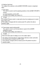
4.7 Connection of module through cable
The method of connecting the AJ65SBT-RPS/RPG module to the CC-Link
system through the cable is shown below.
Termination
resistances
Master module
AJ65SBT-RPS/RPG
Remote module
DA
DB
DG
SLD
FG
DA
DB
DG
FG
SLD
CC-Link dedicated
cable
Local module
DA
DB
DG
FG
SLD
DA
DB
DG
FG
SLD
DA
DB
DG
FG
SLD
Fiber-optic cable
AJ65SBT-RPS/RPG
Optical
interface
Optical
interface
Termination
resistances
CC-Link dedicated
cable
Termination
resistances
Termination
resistances
CC-Link dedicated
cable
Important
In each segment, ensure to use the same type of CC-Link dedicated cables.
If different types of cables are used, normal data transmission will not be assured.
POINT
• Ensure to connect the terminating resistances to both end modules of each
segment.
In addition, connect them between DA and.
(The terminating resistances are furnished with the module.)
• The terminating resistances vary according to the type of cables in use.
For detail, refer to the User's Manual of the applicable master module.
• Connect the shield cable of the CC-Link dedicated cable to "SLD" of each module,
and ground both ends of the cable through "FG" to a class-D (class 3) ground.
SLD and FG are wired to each other inside the module.