•
A1SJ71AR21
Product name
Quantity
A1SJ71AR21 data link module
1
(3) The following table lists PLC CPUs applicable to the A1SJ71AP21/
AR21 and numbers of mountable modules.
Applicable PLC CPU
No. of Mountable Modules
A1SCPU, A1SJCPU-S3, A2SCPU, A1SHCPU,
A1SJHCPU, A2SHCPU
1
A2ASCPU(S1), A2USHCPU-S1, Q2ASCPU(S1),
Q2ASHCPU(S1)
2
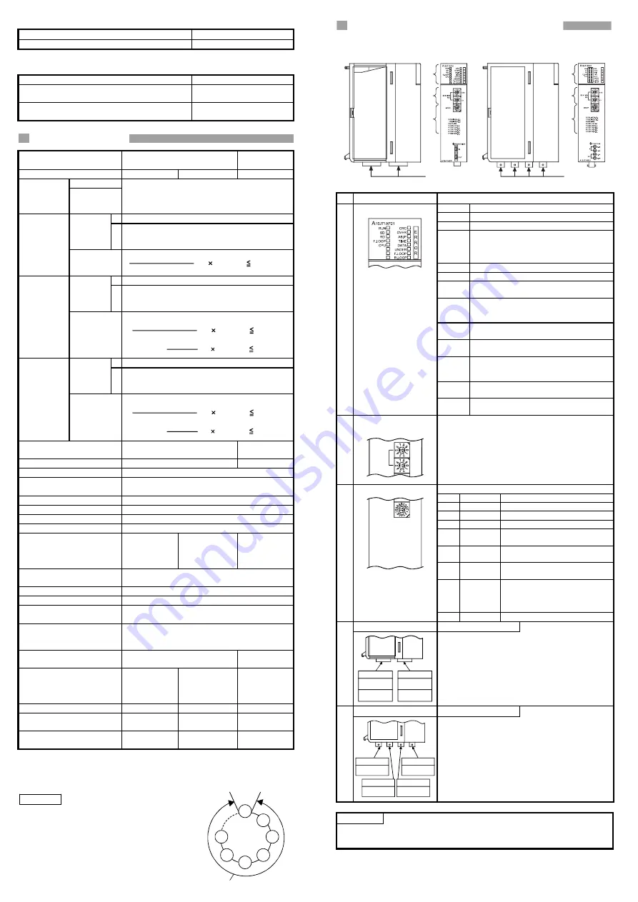
2. Specification
Item
Fiber-Optic Cable Data Link
Coaxial Cable
Data Link
Model A1SJ71AP21
A1SJ71AP21-S3
A1SJ71AR21
Input (X)
Max. number
of link points
used per
station
Output (Y)
Up to the max. I/O points for the CPU used
B 1024points
(128bytes)
Max.
number of
link points
per system
W 1024points
(2048bytes)
MELSECNET
Mode
Max. number
of link points
per station
+ 2 W(points) 1024bytes
Y(B(points)
8
B 4096points
(512bytes)
Max.
number of
link points
per system
W 4096points
(8192bytes)
MELSECNET
II Mode
Max. number
of link points
per station
first half:
+ 2 W(points) 1024bytes
Y(B(points)
8
second half:
+ 2 W(points) 1024bytes
B(points)
8
B 4096points
(512bytes)
Max.
number of
link points
per system
W 4096points
(8192bytes)
MELSECNET
II Composite
Mode
Max. number
of link points
per station
first half:
+ 2 W(points) 1024bytes
Y(B(points)
8
second half:
+ 2 W(points) 1024bytes
B(points)
8
Internal current consumption
(5V DC)
0.33A 0.80A
Weight 0.30kg
0.33kg
No. of occupied I/O points
32points
System's allowable
momentary power failure time
Within 20ms
Communication speed
1.25Mbps
Communications method
Half-duplex bit serial
Synchronous method
Frame synchronous
Transmission path method
Duplex loop
Overall loop distance
Max. 10km
(32810ft)
(1km (3281 ft)
station intervals)
Max. 10km
(32810ft)
(2km (6562ft)
station intervals)
Max. 10km
(32810ft)
(500m (1640.5ft)
station intervals)
Number of connectable
stations
Max. 65 stations/loop (1 master station, 64
local/remote I/O stations)
Demodulation method
CMI
Transmission format
Conforms to HDLC (frame method)
Error control system
Retry due to CRC (generating polynomial X
16
+ X
12
+ X
5
+ 1) and time over
RAS function
The loopback function checks error detection and
cable breakage.
The diagnostic function checks the self link line
Connector
2-core optical connector plug
(Arranged by user
*1
)
---
Cable used
SI optical fiber
cable
H-PCF optical
fiber cable
GI optical fiber
cable
3C-2V, 5C-2V
equivalent
Transmission loss
Max. 12dB/km
Max. 3dB/km
---
Sending level
-17 to -11 dBm
(peak value)
-17 to -10 dBm
(peak value)
---
Receiving level
-32 to -11 dBm
(peak value)
-29 to -10 dBm
(peak value)
---
*1: Specialised skill and specific tools are required to connect the connector to the
opticalfiber cable; the connector itself is a custom product. Please contact your
nearest Mitsubishi Electric System & Service Corporation when purchasing these
products.
REMARK
1) The overall loop distance refers to the distance from
the master station sending port to the master station
receiving port via slave stations.
For both the fiber optic cables and coaxial cables,
The overall loop distance is a maximum of 10km
(32810ft.).
2) For general specifications of the date link system,
refer to the user's manual for the PLC CPU module
that is to be used.
Overall distance
M
L1
R2
L3
R4
R5
L6
3. Names and Settings of Each Part
A1SJ71AP21(-S3) A1SJ71AR21
1)
2)
3)
4)
1)
2)
3)
5)
No. Name Description
RUN
ON when data link is normal
SD
ON during data transmission
RD
ON during data reception
F.LOOP
•
ON while data are received from the
forward loop side
•
OFF while data are received from the
reverse loop side
CPU
ON during communication with PLC CPU
CRC
ON during code check of received data
OVER
ON indicating an error when receive data
processing is delayed
AB.IF
ON indicating an error when too many
consecutive 1s are received or when the
length of received data is too short
TIME
ON indicating an error when the data link
monitoring timer is activated
DATA
ON indicating an error when erroneous data
of 2k bytes or more are received
UNDER ON indicating an error when the internal
processing of send data is not done at the
fixed intervals
F.LOOP Turns ON by a reception error on the forward
loop side
1) LED
R.LOOP Turns ON by a reception error on the reverse
loop side
2) Station number setting
switches
X10
X1
STATION
NO.
Set a station number within a range from 00 to 64.
(factory set: 00)
•
master station 00
local station
01 to 64
X10
Set a tens digit.
X1
Set a units digit.
Select a mode from the following. (factory set: 00)
No. Mode
Description
0
On-line
Data link with automatic return
1
On-line
Data link without automatic return
2
Off-line
Puts this station into cut-off status.
3 Forward
loop test
Checks the forward loop in the
entire data link system.
4 Reverse
loop test
Checks the reverse loop in the
entire data link system.
5,6 Station-to-
station test
Checks a line between 2 adjacent
stations.
7 Self-
loopback
test
Checks hardware of the data link
module, including sending/
receiving circuits in the
communication system.
3) Mode
setting
switch
MODE
0:ONLINE(A.R.)
1:ONLINE(U.R.)
2:OFFLINE
3:TEST 1(F.L.)
4:TEST 2(R.L.)
5:TEST 3(B.M.)
6:TEST 4(B.S.)
7:TEST 5(S.R.)
8 to F
---
Use prohibited
Connector For
A1SJ71AP21(-S3)
4)
IN
Reverse loop
sending
Forward loop
receiving
OUT
Forward loop
sending
Reverse loop
receiving
Optical fiber cable connector
Connector For
A1SJ71AR21
5)
IN R-SD
OUT R-RD
Reverse loop
receiving
Reverse loop
sending
OUT F-SD
IN F-RD
Forward loop
sending
Forward loop
receiving
Coaxial cable connector
POIN
T
For details on the settings and the operating method in test mode, refer to the type
MELSECNET, MELSECNET/B Data Link System Reference Manual.


