6A1 ENGINE (E - W) -
Rocker Cover and Camshaft <MIVEC>
11A-10-5
CAMSHAFT
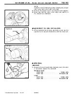
(1) Measure the cam heights. If the specified limit is exceeded,
replace the camshaft.
NOTE
Each camshaft has an identification mark on its rear end
surface.
( ): Identification mark
Standard value
Limit
IN (3)
L
34.34 mm
33.84 mm
H
36.46 mm
35.96 mm
EX (C)
L
34.40 mm
33.90 mm
H
35.86 mm
35.36 mm
VALVE CLEARANCE ADJUSTMENT
NOTE
Adjust the valve clearance for each cylinder and for both
intake and exhaust valves with the piston at the compression
stroke top dead center.
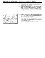
(1) Bring the No. 1 cylinder piston into the compression stroke
top dead center.
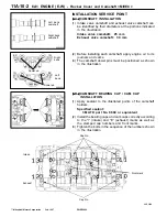
(2) Use the special tool to loosen the adjusting screw.
(3) Insert a thickness gauge of the thickness specified below
between the low-speed cam (narrow cam) and roller.
Intake
0.10 mm
. . . . . . . . . . . . . . . . . . . . . . . . . . . . . . . . . . . . . . . . . . . . . . . . . . . .
Exhaust
0.13 mm
. . . . . . . . . . . . . . . . . . . . . . . . . . . . . . . . . . . . . . . . . . . . . . . . .
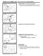
(4) Screw in one of the two adjusting screws until it comes
into contact with the valve (when the turning torque
changes).
PWEE9622
E
Feb. 1997
Mitsubishi Motors Corporation
6AE0227
Valve
9N0058
21 mm
16 mm
6AE0228
High-speed cam (H)
Identification
mark location
Low-speed
cam (L)
6AE0285
Thickness gauge
MB991477


