background image


MITSUBISHI 
ELECTRIC


2033C SERIES UPS 

OWNERS / TECHNICAL MANUAL


Page Number: 

3-9 


MITSUBISHI ELECTRIC 2033C SERIES UPS 


3.5  Operating Procedures 


A)  UPS Start-up Procedure  

1.  Close External Input Circuit Breaker (User supplied. Refer to warning 2). 

2.  The “BYP.OP.” illuminates and power is supplied to the critical load from the static bypass 

line automatically. 

3.  Within ten (10) seconds, the “INV.OP.” LED flashes and the Inverter starts. The UPS will 

automatically transfer the load from the static bypass line to the inverter and the “INV.OP.” 

light illuminates. 


NOTE :


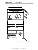
If code “81” is indicated on the FAULT DISPLAY Screen, please check the 

position of EPO button. If EPO button is in the ON position, press the 
button to clear EPO as shown in figure 3.6. Press the “CLEAR” button. If 
code “99” is indicated on the FAULT DISPLAY Screen, press “CLEAR” 
button again.


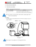
FIGURE 3.6

  EPO button 


                                                EPO “On” position                      Normal position 


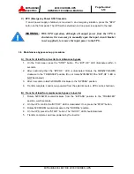
B)  UPS Shutdown Procedure


1.  If a total UPS module (inverter and converter) shutdown is required, press the "STOP" 

button on the front panel. Within 3 seconds the “BYP.OP.” LED will illuminate and the 

UPS will transfer the load to the static bypass line. 


WARNING   : 

Verify the load is OFF if the next step is to be performed .


NOTE :


Power to the critical load is supplied through the static bypass line.  

Power to the critical load will be lost after execution of the next step. The 
load will drop.


2.  If turning off all power to the critical load is desired, open the AC Input Circuit Breaker 

(User supplied.). 


CAUTION : 

In bypass mode, all UPS power terminals are still live. Lethal voltages 

are present. De-energize all external sources of AC and DC power 
before handling UPS.


Содержание 2033C SERIES

Страница 1: ...Revision 2 1 November 11 2003 ALN H0626 MITSUBISHI ELECTRIC AUTOMATION INC UNINTERRUPTIBLE POWER SUPPLY SYSTEM 2033C SERIES OWNERS TECHNICAL MANUAL...

Страница 2: ...MITSUBISHI ELECTRIC 2033C SERIES UPS OWNERS TECHNICAL MANUAL Page Number i MITSUBISHI ELECTRIC 2033C SERIES UPS Preface...

Страница 3: ...OLS AND INDICATORS 2 1 2 1 LCD TOUCH PANEL MONITOR DISPLAY AND KEYPAD 2 1 2 2 EXTERNAL SIGNAL TERMINAL BLOCK 2 5 2 3 EXTERNAL COMMUNICATION CONNECTOR 2 8 3 0 INSTALLATION AND OPERATION 3 1 3 1 TRANSPO...

Страница 4: ...Table 1 2 UPS Module Information 1 14 Table 1 3 Detail of Specifications 1 15 Table 1 4 Rating of Conductor and Fuses 1 16 Table 3 1 How to Transport and Install the System 3 1 Table 3 2 List of UPS W...

Страница 5: ...2 1 11 Figure 1 7 External I F PCB RYDR X 1 11 Figure 1 8 Main Control PCB UPFR K 1 12 Figure 2 1 Operation Display Panel 2 1 Figure 2 2 MAIN MENU Screen 2 2 Figure 2 3 MEASURMENT Screens 2 2 Figure 2...

Страница 6: ...f this manual Warning A warning notice icon conveys information provided to protect the user and service personnel against hazards and or possible equipment damage Caution A caution notice icon convey...

Страница 7: ...descriptions for the installation and operation procedures of the UPS Please read this manual carefully and retain it for future reference This manual contains important instructions for the 2033C Se...

Страница 8: ...The AC input circuit breaker MCCB is to be field supplied and installed Circuit breaker MCCB specifications are as follows Capacity kVA AC input Voltage Vac AC input Rating Aac Recommended Breaker A...

Страница 9: ...own of equipment supported by the UPS The UPS is simple to start up operate and maintain The 2033C Series UPS is available in seven 7 kVA sizes 7 5 10 15 20 30 40 and 50kVA Specifications for each kVA...

Страница 10: ...UPS components which contain the equipment and controls necessary to convert input AC power to regulated DC power required for battery charging and for supplying power to the Inverter INVERTER The UP...

Страница 11: ...eferring to Figure 1 1 Input AC power is converted to DC by the Converter DC power is utilized to charge the UPS battery and to provide power to the Inverter The Inverter converts the DC power to clea...

Страница 12: ...r to the load A fully charged battery will provide power for the specified time at the rated load or longer at reduced load When power is restored after a low battery shutdown the Converter automatica...

Страница 13: ...e bypass switch is shown as 52CS in Figure 1 4 52CS is a two position three point make before break transfer switch 30 40 50kVA Two contactors 52MB 52L are used instead of the 52CS A rotary switch SWM...

Страница 14: ...nce bypass 1 On the front panel press the STOP button The BYP OP LED illuminates within 3 seconds 2 After confirming that the BYP OP LED is illuminated Rotate MBS 52CS SWM clockwise to the TRANSFER po...

Страница 15: ...e Number 1 9 FIGURE 1 5a UPS Parts Location 7 5 20kVA 4 Main PCB UPFR K 3 Relay PCB RYDR X UPS module FRONT VIEW 7 Maintenance bypass transfer switch 52CS Battery 5 AC input AC output terminal Cooling...

Страница 16: ...age Number 1 10 FIGURE 1 5b UPS Parts Location 30kVA 4 Main PCB UPFR K 3 Relay PCB RYDR X UPS module FRONT VIEW 7 Maintenance bypass transfer switch SWM Battery 5 AC input AC output terminal Cooling f...

Страница 17: ...rnal I F PCB RYDR X DPAU 57 DPAU 72 8 SW5 TEST switch RYDR X 10 CN62 RS232C D sub Connector 9 External contact signal terminal block 11 CN64 RS232C D sub Connector 4 Main PCB UPFR K UPS module FRONT V...

Страница 18: ...ay screens 2 Display PCB DPAU 72 Switches on DPAU 72 board FOR SERVICE PERSONNEL ONLY Figure 1 6 8 SW5 TEST switch 3 Relay PCB RYDR X board Signal I F on RYDR X board Figure 1 7 9 External contact sig...

Страница 19: ...be operated by personnel other than an Authorized Service Engineer 9 External contact signal terminal block Terminal block to connect contact signal input output lines to and from external dry contac...

Страница 20: ...15kVA 12kW 20kVA 16kW 30kVA 24kW 40kVA 32kW 50kVA 40kW 208 208 208 208 208 208 208 208 208 208 208 208 208 208 TABLE 1 2 UPS Module Information UPS kVA CABLE ENTRY WIDTH in mm DEPTH in mm HEIGHT in mm...

Страница 21: ...wer Factor 0 8 nominal Power Factor range 0 8 1 0 lagging within output kW rating Voltage THD 2 typical THD at 100 Linear Load 4 typical THD at 100 non linear load Transient Response 3 typical at 100...

Страница 22: ...0A 150A CB2 DC Input Contactor 60A 100A 150A 150A CB3 Static Bypass Input Contactor 60A 100A 150A 150A 52C AC Output Contactor 60A 100A 150A 150A FIU W AC Input Fuse 140A 660V 180A 600V 280A 660V 280A...

Страница 23: ...ouch Panel Monitor Display The Liquid Crystal Display LCD Touch panel Monitor Display indicates power flow measured values and fault and error messages via user selectable display screens MAIN MENU SC...

Страница 24: ...n in Figure 2 3 FIGURE 2 3 MEASUREMENT Screens Each MEASUREMENT Screen includes a MAIN Menu Screen Touch Icon On pressing this MAIN Touch icon the display returns to the MAIN MENU Screen AC Output Mea...

Страница 25: ...as fault alarm History can be displayed as shown in Figure 2 4 The FAULT DISPLAY Touch icon will flash on the MAIN MENU Screen if there are Fault Alarms that have not been restored Pressing the DETAI...

Страница 26: ...Illuminated when power is supplied to load devices by static bypass 5 UPS failure FAILURE red Illuminated when UPS is in fault mode 6 Inverter start START green Inverter start button When pressed the...

Страница 27: ...UPS functions Layout of terminals is shown in Figure 2 6 with a functional description of the input output port presented FIGURE 2 6 External Signal Terminal Block NEC Class2 TB BATTERY TEMP HIGH Opti...

Страница 28: ...when a fault alarm occurs Terminals 7 to 8 Load on Inverter contact Activated when the power is supplied by the inverter Terminals 9 to 10 Load on Bypass contact Activated when the power is supplied b...

Страница 29: ...rature high See below for terminal connection details FIGURE 2 8 Remote Stop Contact Connections Details of input contacts for remote access Terminals 1 to 2 Emergency Stop contact input Used to perfo...

Страница 30: ...ctor is shown in Figure 2 9 FIGURE 2 9 External communication connector NEC Class2 Pin 1 Not used Pin 2 RXD Receive data Pin 3 TXD Transmit data Pin 4 DTR Always high level Pin 5 GND Signal ground Pin...

Страница 31: ...UPS cabinet as shown in Figure 3 1 Fix the UPS unit in place using the four 4 leveling feet Note Do not transport in a horizontal position Cabinets should be maintained upright within 15 of the vertic...

Страница 32: ...side 7 8 200 mm Top side 39 4 1000 mm C Space requirement for routine maintenance Allow for the following space at the time of installation Front 39 4 1000 mm Sides 1 0 25 mm Rear 7 8 200 mm D Battery...

Страница 33: ...cedure for Cable Connections Refer to Table 3 4 for cable sizes I Confirm the capacity of the UPS being installed Identify the input output power terminal blocks as shown in the appropriate Figure 3 2...

Страница 34: ...ger 180 in lbs 20kVA 208V 6 AWG or larger 180 in lbs 6 AWG or larger 180 in lbs 30kVA 208V 2 AWG or larger 180 in lbs 2 AWG or larger 180 in lbs 40kVA 208V 2 0 AWG or larger 180 in lbs 2 0 AWG or larg...

Страница 35: ...BISHI ELECTRIC 2033C SERIES UPS Fig 3 2 UPS Terminal Designation Terminals INPUT A B C N Terminals OUTPUT A B C N Output AC input BATTERY CB3 Static Transfer Switch 52C CB1 FO FI CONVERTER INVERTER UP...

Страница 36: ...ERIES UPS FIGURE 3 3 Input Output Power Terminals 7 5kvA 20kVA ALL POWER TERMINALS USE 1 4 6 MM DIAMETER BOLTS Control printed circuit boards Fan Inverter and Converter 52CS Input Output Power Termina...

Страница 37: ...utput Power Terminals 30kVA Converter Inverter Unit Cooling fan A B C N A B C N Battery Battery Battery Battery RYDR X N P INPUT OUTPUT TRANSFER NORMAL BYPASS MBS DC INPUT Control printed circuit boar...

Страница 38: ...2033C SERIES UPS FIGURE 3 5 Input Output Power Terminals 40kvA 50kVA A B C N A B C N N P AC INPUT AC OUTPUT DC INPUT Grounding bar MBS BYPASS TRANSFER NORMAL RYDR X Control printed circuit boards Conv...

Страница 39: ...n figure 3 6 Press the CLEAR button If code 99 is indicated on the FAULT DISPLAY Screen press CLEAR button again FIGURE 3 6 EPO button EPO On position Normal position B UPS Shutdown Procedure 1 If a t...

Страница 40: ...ront panel press the STOP button The BYP OP LED illuminates within 3 seconds 2 After confirming that the BYP OP LED is illuminated Rotate the MBS 52CS SWM clockwise to the TRANSFER position Do not rot...

Страница 41: ...ection 6 of this manual When faults occur contact the Authorized Mitsubishi Service Representative or call Mitsubishi at 1 800 887 7830 Note The error code indicated on the FAULT DISPLAY Screen of the...

Страница 42: ...he average ambient operating temperature Battery end of life is defined as the state of charge resulting in an ampere hour capacity less than or equal to 80 of nominal capacity Replace battery if capa...

Страница 43: ...codes their description and required action At time of error A Verify and record the occurrence of the alarm Note fault code on the FAULT DISPLAY Screen of the LCD Display Contact Mitsubishi Electric...

Страница 44: ...ge out of range Check AC input voltage 1 Alarm 22 AC input phase rotation error Check AC input voltage 1 Minor Flicker 23 Converter overload Call service engineer 1 Alarm Flicker 24 Converter over cur...

Страница 45: ...58 Control circuit error Call service engineer 1 Minor Flicker 59 Control circuit error Call service engineer 2 Major Lit up 71 Overload Reduce load 1 Alarm Flicker 72 kW overload Reduce load 1 Alarm...

Страница 46: ...ure UPS continues to operate normally but cause of alarm must be identified Over is defined as an overload condition Load will transfer from inverter to the static bypass line and may or may not retur...

Страница 47: ...ter your UPS for warranty purposes please complete the warranty registration form and fax it to the Mitsubishi Electric UPS Systems Group Service Department fax line shown on the registration form Nex...

Страница 48: ...nown Signature Date Which ONE of These Best Describes Your Organization s Number of Employees at This Location is Primary Business Classification Energy Producer __ Education Univ Service __ 1 19 __ 1...

Отзывы: