Mitsubishi Heavy Industries SRK71CF-BN Скачать руководство пользователя страница 18

-

 16 

-

(3)

Unit indication section

        Models All models

RUN light (green)

• Illuminates during operation.

TIMER light (yellow)

Illuminates during TIMER operation.

HI POWER light (green)

Illuminates during HIGH POWER operation.

ECONOMY light (orange)

Illuminates during ECONOMY operation.

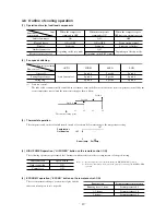
4.2 Unit ON/OFF button

When the remote control batteries become weak, or if the remote control is lost or malfunctioning, this button may be used to turn the

unit on and off.

(1)

Operation

Push the button once to place the unit in the automatic mode. Push it once more to turn the unit off.

(2)

Details of operation

The unit will go into the automatic mode in which it automatically determines, from room temperature (as detected by sensor),

whether to go into the cooling or thermal dry modes.

Function

Room temperature

Operation mode

setting

Fan speed

Flap

   Timer switch

Cooling

About 24ºC

Thermal dry

About 24ºC

Auto

Auto


Continuous

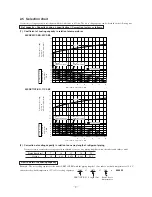
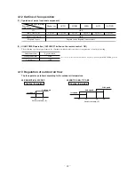
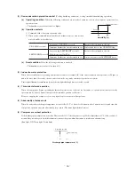
4.3 Power blackout auto restart function

(1)

Power blackout auto restart function is a function that records the operational status of the air-conditioner immediately prior to it

being switched off by a power cut, and then automatically resumes operations at that point after the power has been restored.

(2)

The following settings will be cancelled:

(a)

Timer settings

(b)

High-power operations

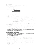
Notes (1) The power blackout auto restart function is set at on when the air-conditioner is shipped from the

factory. Consult with your dealer if this function needs to be switched off.

(2) When power failure ocurrs, the timer setting is cancelled. Once power is resumed, reset the timer.

(3) If the jumper wire (J7) “AUTO RESTART” is cut, auto restart is disabled. (See the diagram at right)

Unit ON/OFF button

Jumper wire (J7)

EXTERNAL INPUT

WIRED REMOCON

OPE PERMISSION

CUSTOM

AUTO RESTART

LO TEMP

DIRT PREVENT

COOL ONLY

HI CEIL

PANEL

50/60

Содержание SRK71CF-BN

Страница 1: ... 3 WALL MOUNTED TYPE ROOM AIR CONDITIONER TECHNICAL MANUAL Collection data Manual No 06 SRK T 062 Split system air cooled cooling only type SRK52CF BN 71CF BN SRK52CF BP 71CF BP ...

Страница 2: ...line of dehumidifying operation 20 4 10 Outline of automatic operation 21 4 11 Set temperature selection 21 4 12 Outline of fan operation 22 4 13 Regulation of outdoor air flow 22 4 14 Stop mode 23 4 15 External control remote display control of input signal 24 4 16 Operation permission prohibition control 25 4 17 Protective control function 25 4 18 List of indoor unit jumper selections 28 5 APPLI...

Страница 3: ...eft right air swing at the same time results in a multi directional air flow Memory flap Once the flap louver position is set the unit memorizes the position and continues to operate at the same position from the next time 2 Automatic operation When the remote control switch is set on auto it will either automatically decide operation mode such as cooling and thermal dry or operate in the operatio...

Страница 4: ...l Microcomputer thermostat Pilot lamp RUN Green TIMER Yellow HI POWER Green ECONO Orange Safety equipment O D mm in Liquid line φ6 35 1 4 Gas line φ15 88 5 8 Connecting method Flare connecting Attached length of piping Liquid line 0 70m Gas line 0 63m Insulation Necessary Both sides Drain hose Connectable Power source supply Terminal block Screw fixing type Size Core number 1 5 mm2 4 cores Includi...

Страница 5: ...om temperature control Microcomputer thermostat Pilot lamp RUN Green TIMER Yellow HI POWER Green ECONO Orange Safety equipment O D mm in Liquid line φ6 35 1 4 Gas line φ15 88 5 8 Connecting method Flare connecting Attached length of piping Liquid line 0 70m Gas line 0 63m Insulation Necessary Both sides Drain hose Connectable Power source supply Terminal block Screw fixing type Size Core number 1 ...

Страница 6: ...ol Microcomputer thermostat Pilot lamp RUN Green TIMER Yellow HI POWER Green ECONO Orange Safety equipment O D mm in Liquid line φ6 35 1 4 Gas line φ15 88 5 8 Connecting method Flare connecting Attached length of piping Liquid line 0 70m Gas line 0 63m Insulation Necessary Both sides Drain hose Connectable Power source supply Terminal block Screw fixing type Size Core number 1 5 mm2 4 cores Includ...

Страница 7: ...trol Microcomputer thermostat Pilot lamp RUN Green TIMER Yellow HI POWER Green ECONO Orange Safety equipment O D mm in Liquid line φ6 35 1 4 Gas line φ15 88 5 8 Connecting method Flare connecting Attached length of piping Liquid line 0 70m Gas line 0 63m Insulation Necessary Both sides Drain hose Connectable Power source supply Terminal block Screw fixing type Size Core number 1 5 mm2 4 cores Incl...

Страница 8: ...mes h ON and OFF interval Max 3 minutes Outdoor air temperature Upper lower limits Vertical height difference between outdoor unit and indoor unit Item Models 1 Indoor unit Models SRK52CF BN 71CF BN 52CF BP 71CF BP VIEW A A 17 3 60 150 4 43 5 55 64 48 9 Piping hole right left 3 248 55 4 19 51 2 55 Terminal block 1090 Unit mm 318 77 44 5 7 7 299 106 8 5 301 8 25 50 Installation board 450 50 25 Pipi...

Страница 9: ...ø15 88 5 8 Ground terminal 124 34 6 20 2 0 42 7 100 3 15 640 14 2 Outdoor unit Models SRC52CF BN 52CF BP Models SRC71CF BN 71CF BP Unit mm 380 19 24 750 103 5 48 5 580 880 418 340 88 150 150 27 32 310 223 47 5 61 61 2 R7 5 60 15 Drain holes Service valve Gas Flare fitting ø15 88 5 8 Service valve Liquid Flare fitting ø6 35 1 4 Terminal block 3 0 165 5 25 Unit mm ...

Страница 10: ...changer sensor Compressor Capillary tube Capillary tube Strainer Accumulator Service valve Gas Electronic expansion valve except for 52CF BN Outdoor unit Indoor unit Room temp sensor Humidity sensor Heat exchanger Flare connecting Heat exchanger sensor Piping Liquid ø6 35 Piping Gas Check joint Service valve Liquid Flare connecting Discharge pipe temp sensor Cooling cycle Muffler Outdoor air temp ...

Страница 11: ...eratures 2 Correction of cooling capacity in relation to one way length of refrigerant piping It is necessary to correct the cooling capacity in relation to the one way piping length between the indoor and outdoor units 16 18 20 22 21 25 30 35 40 0 6 0 7 0 8 0 9 1 0 1 1 1 2 1 3 45 50 54 24 Indoor air W B temperature C W B Cooling Applicable range Coefficient of cooling capacity in relation to temp...

Страница 12: ...ock Operation indication DC12 Heating indication DC12 ON indication for CM DC12 Check indication DC12 Distant operation Humidity sensor Heat exch sensor Outdoor unit Outdoor air temp sensor Discharge pipe temp sensor Varistor Electronic expansion valve Diode stack Auxiliary relay Th3 Th4 Th5 Th6 ZNR EEV DS 52X1 4 CC CFO TB XR1 XR2 XR3 XR4 XR5 Parts name BL OR Y G Black Blue Orange Yellow Green WH ...

Страница 13: ...DC12 Heating indication DC12 ON indication for CM DC12 Check indication DC12 Distant operation Humidity sensor Heat exch sensor Outdoor unit Outdoor air temp sensor Discharge pipe temp sensor Varistor Electronic expansion valve Diode stack Auxiliary relay Th3 Th4 Th5 Th6 ZNR EEV DS 52X1 5 CC CFO TB XR1 XR2 XR3 XR4 XR5 Parts name BL OR Y G Black Blue Orange Yellow Green WH White RD Red GR Green Y Y...

Страница 14: ...cation DC12 Heating indication DC12 ON indication for CM DC12 Check indication DC12 Distant operation Humidity sensor Heat exch sensor Outdoor unit Outdoor air temp sensor Discharge pipe temp sensor Varistor Electronic expansion valve Diode stack Auxiliary relay Th3 Th4 Th5 Th6 ZNR EEV DS 52X1 4 CC CFO TB XR1 XR2 XR3 XR4 XR5 Parts name BL OR Y G Black Blue Orange Yellow Green WH White RD Red GR Gr...

Страница 15: ...n DC12 Heating indication DC12 ON indication for CM DC12 Check indication DC12 Distant operation Humidity sensor Heat exch sensor Outdoor unit Outdoor air temp sensor Discharge pipe temp sensor Varistor Electronic expansion valve Diode stack Auxiliary relay Th3 Th4 Th5 Th6 ZNR EEV DS 52X1 5 CC CFO TB XR1 XR2 XR3 XR4 XR5 Parts name BL OR Y G Black Blue Orange Yellow Green WH White RD Red GR Green Y...

Страница 16: ...N mode ON TIMER button This button selects ON TIMER operation TEMPERATURE button This button sets the room temperature This button changes the present time and TIMER time OFF TIMER button This button selects OFF TIMER operation RESET switch Switch for resetting microcomputer OPERATION MODE indicator Indicates selected operation with lamp Auto Cool Fan Dry TEMPERATURE indicator Indicates set temper...

Страница 17: ...de operation settings RESET switch Press this switch while making settings to go back to the previous operation This switch is also used to reset the FILTER CLEANING message display Press this switch after cleaning the air filter Central control display Displayed when the air conditioning system is controlled by the option controller Timer operation display Displays the settings related to timer o...

Страница 18: ...Fan speed Flap Timer switch Cooling About 24ºC Thermal dry About 24ºC Auto Auto Continuous 4 3 Power blackout auto restart function 1 Power blackout auto restart function is a function that records the operational status of the air conditioner immediately prior to it being switched off by a power cut and then automatically resumes operations at that point after the power has been restored 2 The fo...

Страница 19: ...rd directions continuously 2 Swing louver Louver moves in left and right directions continuously 3 When not operating The flap returns to the position of air flow directly below when operation has stopped 4 Multi directional Air Flow up down air scroll and left right air scroll Activating both up down air swing and left right air swing at the same time results in a multi directional air flow Up do...

Страница 20: ...dehumidifying in the auto mode However the operation of item 1 above is performed during the dehumidifying in the auto mode 3 During the comfortable timer operation both the run light and timer light illuminate and the timer light goes off after expiration of the timer ON setting time If the difference Room temperature Setting tempera ture is 4ºC the correction value is found to be 5 min utes from...

Страница 21: ...ed 6 Speed 6 AUTO HIGH MED Speed 4 Speed 4 Speed 4 LOW Flow control Fan speed switching Speed 6 Speed 4 Thermostat setting point Speed 8 1 2 3 4 3 Thermostat operation The compressor and outdoor fan and turned on and off as shown below according to the temperature setting 4 HIGH POWER operation HI POWER button on the remote control ON The following operation is performed for 15 minutes without rel...

Страница 22: ...or fan Start Temperature check Speed 4 4 8 0 Speed 1 20 seconds minutes B Block Compressor and outdoor fan ON OFF OFF Indoor fan Start Temperature check Speed 4 8 0 minutes A Block Compressor and outdoor fan ON OFF OFF Indoor fan Start Temperature check 4 8 0 Speed 1 20 seconds minutes 20 seconds D Block Compressor and outdoor fan ON OFF OFF Indoor fan Start Temperature check Speed 4 Speed 1 8 3 0...

Страница 23: ...can lower the set temperature 2º lower than the set temperature in the remote control s display 1 Modifying the indoor unit s printed circuit board Take out printed circuit board from the control box and cut jumper wire J8 using wire cutters After cuting of the jumper wire take measures to prevent contact with the other the lead wires etc 2 Setting temperature can be adjusted within the following ...

Страница 24: ... louver control Speed 6 Speed 4 Speed 2 High power AUTO HIGH MED LOW ECONO Functional components Fan speed switching Indoor unit fan Outdoor unit fan Compressor Speed 9 fixed OFF OFF Note 1 Protective functions will actuate with priority even during the HIGH POWER operation 4 13 Regulation of outdoor air flow The fan operates as follows according to the outdoor air temperature S SRK52CF BN 52CF BP...

Страница 25: ... Cooling cooling oriented dehumidifying Operation Stop instructions All stop Stop instructions Restart When the complete stop command given when there is and abnormal stoppage command When stoppage occurs due to thermostat operation switching operations and protective function operations 470 pulse 150 pulse 1 min 1 min 3 min 2 min 55 sec 2 min 55 sec 470 pulse 4 14 Stop mode ...

Страница 26: ...of input signal Control of input signal switch input timer input connectors CNT are provided on the control circuit board of the indoor unit However when the operation of air conditioner is under the Center Mode the remote control by CnT is invalid a If the factory settings Jumper wire J1 EXTERNAL INPUT on the PCB are set or LEVEL INPUT is selected in the wired remote control s indoor unit setting...

Страница 27: ...tion depends on 1 above When the jumper wire J3 is short circuited Normal operation is enable when shipping When CnT input is set to ON the operation starts and if the input is set to OFF the operation stops For the CnT and remote control inputs the input which is activated later has priority and can start and stop the operation When the jumper wire J3 is released Permission Prohibition mode When ...

Страница 28: ...has passed the thermal operation is effective However stopping the compressor via a stop signal or protection control has priority 5 Abnormality of outdoor unit When the indoor heat exchanger temperature does not fall to 25 C or below for 40 minutes after 5 minutes have elapsed since the compressor operation start the abnormality stop occurs The timer light flashes 2 times 6 Compressor overheat pr...

Страница 29: ...ror indication is displayed Run light 1 time flash Timer light ON c Outdoor heat exchanger temperature sensor If the temperature detected by the outdoor heat exchanger temperature sensor is 64ºC or lower continuously for 15 seconds or longer while operation is stopped an error indication is displayed Run light keep flashing Timer light 2 time flash d Outdoor air temperature sensor If the temperatu...

Страница 30: ...7 J8 J9 J10 J11 J12 J13 Page 24 Page 37 Page 25 Page 17 Page 16 Page 21 External input switching Wired remote control Operation permission prohibition Custom cord switching No function Auto restart Set Temperature Selection No function EXTERNAL INPUT WIRED REMOCON OPE PERMISSION CUSTOM BLANK BLANK AUTO RESTART LO TEMP DIRT PREVENT COOL ONLY HI CEIL PANEL 50 60 LEVEL INPUT Disabled Normal operation...

Страница 31: ...g the safety standards related to electrical equipment and local regulations as well as the installation instructions and that only exclu sive use circuits are used Insufficient power source circuit capacity and defective installment execution can be the cause of electric shocks and fires Accurately connect wiring using the proper cable and insure that the external force of the cable is not conduc...

Страница 32: ... unit s operating sound will not be a nuisance to the neighborhood c A place where servicing space can be secured d A place where vibration will not be enlarged e Avoid installing in the following places A place near the bedroom and the like so that the operation noise will cause no trouble A place where there is possibility of flammable gas leakage A place exposed to strong wind In a salt laden a...

Страница 33: ...gth Adjust so that board will be level by turning the board with the standard hole as the center Standard hole c Install the sleeve Inserting sleeve Sleeve Inclined Sealing plate Note 1 Drill a hole with incline of 5 degree from indoor side to outdoor side Indoor side Outdoor side Cut off the sleeve collar in case of drawing piping out to rear Cut off the sleeve collar that can be seen from beneat...

Страница 34: ...es H05RNR4G1 5 Example H Harmonized cable type 05 300 500 volts R Natural and or synth rubber wire insulation N Polychloroprene rubber conductors insulation R Standed core 4 Number of conductors G One conductor of the cable is the earth conductor yellow green 1 5 Section of copper wire mm2 Wiring Clamp Lid Terminal block When the hose is extended to left and taken out from the rear center Piping D...

Страница 35: ...en it is exposed indoor Drain hose c Fixing of indoor unit How to remove the indoor unit from the installation board 1 Push up at the marked portion of the indoor unit base lower latch and slightly pull it toward you both right and left hand sides The indoor unit base lower latch can be removed from the installation board 2 Push up the indoor unit upward So the indoor unit will be removed from the...

Страница 36: ...ve the flared nuts on both liquid and gas sides Install the removed flared nuts to the pipes to be connected then flare the pipes Dimension A Liquid side φ6 35 9 0 mm Gas side φ15 88 19 4 mm Press Remove Remove Do not turn 2 Connection of refrigerant piping Indoor unit side Connect firmly gas and liquid side pipings by Torque wrench Outdoor unit side Connect firmly gas and liquid side pipings by T...

Страница 37: ...ts of both indoor and outdoor Please use an anti reverse flow type vacuum pump adapter so as to prevent vacuum pump oil from running back into the system Oil running back into an air conditioning system may cause the refrigerant cycle to break down Additional refrigerant charge When refrigerant piping exceeds 7m conduct additional refrigerant charge by weight after refrigerant piping completion Ad...

Страница 38: ...rong light such as direct sunlight illumination etc or dust is deposited on it or it is used behind a curtain etc or less 5 m o r l e s s Wireless remote control 5 m or less or less 5 6 Precautions for wireless remote control installation and operation 1 Wireless remote control covers the following distances a When operating facing the air conditioner or less If the distances exceed the area indic...

Страница 39: ... printed circuit board a Remove the air inlet panel Refer to the installa tion directions b Remove the front panel Refer to the installa tion directions c Remove the control box Remove the screw and the latch and open the control lid Remove the flap connector the louver connec tor the fan motor connector the earth and the sensor Remove the screw fixing the control box Remove the control box from t...

Страница 40: ... Replace the top casing as before f Use a cord clamp to attach the remote con trol cord to the wall g Set the functions according to the types of indoor unit See Section Function Setting Thin walled part Upper Lower Lower case Upper Lower Lower case Upper Lower Board Wiring X Y Z Red White Black Upper case Remote control cord Electrical box Not included Upper Lower Cable outlet Lower case Upper Lo...

Страница 41: ...L INPUT PULSE INPUT NORMAL OPERATION VALID NORMAL OPERATION TEMP SHIFT 3 C LOW FAN STOP LOW FAN Intermittent operation TEMP Hi TEMP Lo FAN CONTROL ON FAN CONTROL OFF Function description B Setting C Function number A Function description B Setting C POWER FAILURE COMPENSATION SET OPERATION PERMISSION PROHIBITED Notes 1 2 3 Setting marked with 嘷 are the default setting Setting marked with are those...

Страница 42: ...n Function number A Function description B from the list of remote control unit functions will be displayed one by one Select a desired function 3 Press the SET button The screen display will be switched as follows SETTING Setting C ex AUTO RUN ON 4 Press either or button A list of Settings C will be displayed one by one Select your desired setting 5 Press the SET button The selected setting is di...

Страница 43: ... seconds then followed by SET COMPLETE and the function setting process is completed Then the screen display will be switched to Function number A Function description B so if you want to continue to set another function repeat the step as explained above To finish the function setting process please proceed to Step 8 8 Press AIR CON No button The screen display will go back to the indoor unit sel...

Страница 44: ...Press the button once The display will change to TEMP RANGE c Press the SET button to enter the temperature range setting mode d Using the or button select Hi LIMIT SET or Lo LIMIT SET the press the SET button e If Hi LIMIT SET is selected 1 The display changes from SET UP Hi LIMIT 22ºC flashing 2 Using the button select the upper limit value Display example Hi LIMIT 22ºC flashing 3 Press the SET ...

Страница 45: ...ection to the terminal block for remote control polar total length of wires 600 m maximum No Name ot the recommended signal wire 1 Shielding wire 2 Vinylcabtire round cord 3 Vinyl cabtire round cable 4 Control vinyl insulated vinyl sheath cable Master Slave Address SW 3 1 ON Master OFF Slave Shielding wires 100 200 m 0 5 mm2 3 core wires 300 m 0 75 mm2 3 core wires 400 m 1 25 mm2 3 core wires 600 ...

Страница 46: ...ve open 3 Troubleshooting procedure If the air conditioner does not run at all If the air conditioner does not run at all diagnose the trouble using the following troubleshooting procedure If the air conditioner is running but breaks down proceed to troubleshooting step 4 Important When all the following conditions are met we say that the air conditioner will not run at all 1 The Run light does no...

Страница 47: ...ustomer complaints Judge the conditions in comparison with the contents of the complaints Confirm the contents of the customer complaint Check the self diagnosis display Eliminate the cause of the trouble and perform an operation check Replace the faulty component then perform an operation check Identify the faulty component by using the check procedure corresponding to the content of the trouble ...

Страница 48: ... value of the discharge pipe sensor exceeds the set value The air conditioner stops Defective fan motor poor connector connection Gas shortage defective discharge pipe sensor closed service valve Indoor fan motor error Over heat of compressor When a sensor wire disconnection is detected while operation is stopped If a temperature of 64o C or lower is detected for 15 seconds it is judged that the w...

Страница 49: ...4 65 10 135 1 3 Sensor temperature characteristics Discharge pipe temp outdoor unit heat exchanger temp Indoor fan motor error Defective fan motor connector poor connection defective PCB Is connector connection good YES NO NO Is the output of the indoor unit s printed circuit board normal Normal NO YES YES Correct connector connection Is DC fan motor resistance value good Replace indoor PCB Replac...

Страница 50: ...n Wiring error including power cable defective indoor outdoor unit PCB Does error persist after power reset Are the lines connecting the indoor and outdoor units connected normally Is DC 0 Approx 12V detected between 2 3 terminals on indoor unit terminal block YES YES NO NO YES NO Trouble by transient cause not unit trouble Correct improper wire connection on indoor outdoor unit Defective indoor u...

Страница 51: ...or stop Heat exchanger sensor Outdoor air temperature sensor Discharge pipe sensor Compressor overload protection is disabled Can be operated 7 Phenomenon observed after shortcircuit wire breakage on sensor a Indoor unit Phenomenon Sensor Shortcircuit Broken wire Cooling Release of continuous compressor operation command Compressor stop Cooling Abnormality of outdoor unit Operation mode Room tempe...

Страница 52: ... the indoor unit s fan motor or the circuit board is broken down 1 Indoor unit printed circuit board output check a Turn off the power b Remove the front panel then disconnect the fan motor lead wire connector c Turn on the power If the unit operates when the ON OFF button is pressed if trouble is detected after the voltages in the following figure are output for approximately 30 seconds it means ...

Страница 53: ...ne 1 display it is basically normal 1 Is remote control normal YES Again pushing operating switch Operating the unit NO Does unit ON OFF button operates Operating the unit NO NO YES YES Remote control defects Abnormality is not found Replace the display Control problem on main unit Is the unit operable with remote control Defective remote control NO YES Normal ...

Страница 54: ... then immediately retighten it after observing that gas is blow out from the loosened portion e Open the valve 1 and 3 after discharging air from the charge hose A then the gas refrigerant begins flowing from the cylinder into the unit Be sure to erect the refrigerant cylinder upright to let gas refrigerant flow into the unit f When refrigerant has been charged into the system to some extent refri...

Страница 55: ... 2 WALL MOUNTED TYPE ROOM AIR CONDITIONER No 034 1 1A RO Air Conditioning Refrigeration Systems Headquarters 16 5 2 chome Kounan Minato ku Tokyo 108 8215 Japan Fax 03 6716 5926 ...

Отзывы: