


-
-
'16 • SRK-T-192
'09•SRK-DB-087D
(6)
ޓ
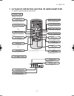
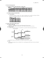
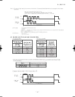
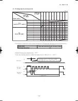
3D auto operation
(a)
(i)
(ii)
(b)
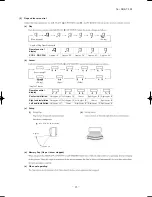
Cooling
Air flow selection
Operation mode
AUTO
HI
MED
LO
Indoor temp. – Setting temp. >5°C
Indoor temp. – Setting temp. 5°C
HIGH POWER
AUTO
HI
MED
LO
<
=
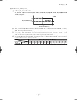
Flap
Louver
Cooling
Up/down Swing
Wide (Fixed)
Flap
Louver
Cooling
Left/right Swing
Horizontal blowing (Fixed)
Flap
Louver
Cooling
Up/down Swing
Center (Fixed)
Wide (Fixed)
Flap
Louver
Cooling
Horizontal blowing (Fixed)
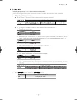
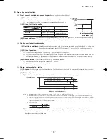
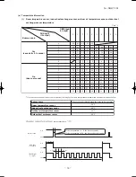
Operation mode
Indoor temp. – Setting temp. 2°C
Cooling
Air flow direction contorol
2°C < Indoor temp. – Setting temp. 5°C
Indoor temp. – Setting temp. > 5°C
The control in 4) continues.
dehumidifying
dehumidifying
Control returns to the control in 2).
Control returns to the control in 1).
<
=
<
=
Wide (Fixed)
Flap
Air flow selection
Louver
According to
dehumidifying
operation.
Horizontal blowing (Fixed)
1)
2)
3)
4)
5)
3
4
o
'09•SRK-DB-087D
(b) Sleep timer operation
(7)
ࠉ
Timer operation
(a) Comfortable timer setting (ON timer)
(c) OFF timer operation
(8)
ࠉ
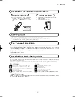
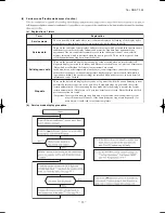
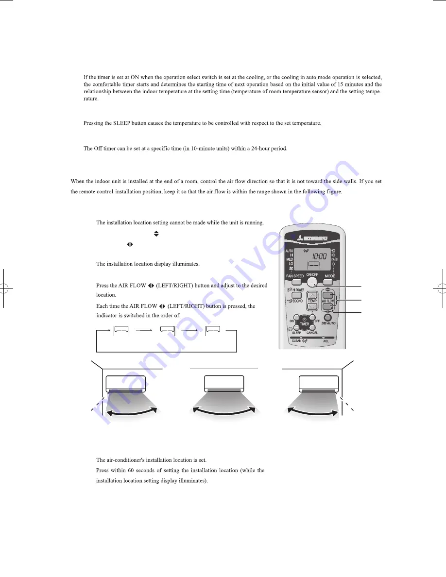
Installation location setting
(a) Setting
(i) If the air-conditioning unit is running, press the ON/OFF button to stop.
(ii) Press the AIR-FLOW
(UP/DOWN) button and the
AIR FLOW
(LEFT/RIGHT) button together for 5 seconds
or more.
(iii) Setting the air-conditioning installation location.
(iv) Press the ON/OFF button.
Airflow range
Airflow range
Airflow range
(Left End Installation)
(Center Installation)
(Right End Installation)
(Center Installation)
(Right End Installation) (Left End Installation)
L
,
LY
LL
LLL
– 16 –
Installation location setting
3
Setting the air-conditioning installation location.
Each time the AIR FLOW (LEFT/RIGHT) button is pressed, the
indicator is switched in the order of:
Press the AIR FLOW (
LEFT/RIGHT) button and adjust to the
desired location.
Take the air conditioning unit’s location into account and adjust the left/right airflow range to maximize air-conditioning.
(Center Installation)
(Right End Installation) (Left End Installation)
2
Press the AIR FLOW (UP/DOWN) button and the
AIRFLOW (LEFT/RIGHT) button together for 5 seconds
or more.
The installation location display illuminates.
1
If the air conditioning unit is running, press the ON/OFF
button to stop
.
The installation location setting cannot be made while the unit is running.
4
Press the ON/OFF button.
The air-conditioner's installation location is set.
Press within 60 seconds of setting the installation location (while the
installation location setting display illuminates).
Press within
60 sec.!
Air conditioner installation location and airflow range
The diagram below indicates the airflow ranges corresponding to the air-conditioner's installation location. Consider your room's layout and
set the airflow range to maximize conditioning effectiveness.
Airflow range
Airflow range
Airflow range
(Left End Installation)
(Center Installation)
(Right End Installation)
General Information
• mark will be displayed on the display panel while the air conditioner is in operation, regardless of the installation location of the unit.
• When installation location of the air conditioner had been set once, installation location will be memorized into the unit even if
unplugging the power cord. Please set it with a remote control again in case of changing the installation location of the unit.
• The installation location setting can not be performed while the unit is in operation.
RMA012A032_En.p65
04/05/2010, 17:26
16
Содержание SRK18YLV-S1
Страница 2: ......
Страница 3: ...TECHNICAL MANUAL ...
Страница 9: ... 16 SRK T 192 3 Wireless remote control Unit mm 60 17 3 150 ...
Страница 53: ... 50 16 SRK T 192 ...
Страница 54: ... 51 16 SRK T 192 PARTS LIST INDOOR UNIT SRK18YLV S1 OUTDOOR UNIT SRC18YLV S1 ...
Страница 57: ... 54 16 SRK T 192 CRAE0254 21 17 23 24 22 18 1 8 5 7 6 3 2 4 15 9 11 12 16 19 13 14 20 25 10 HEAT EXCH CONTROL ...
Страница 59: ... 56 16 SRK T 192 CRBE0294 6 13 11 18 12 15 16 3 17 14 2 4 9 8 7 5 1 8 8 10 PANEL FAN ASSY ...


