


-
-
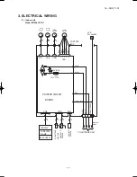
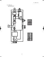
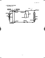
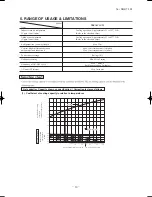
'16 • SRK-T-192
①
A place where good air circulation can be obtained and where rain,
snow or sunshine will not directly strike the unit.
②
A place where discharged hot air or unit’s operating sound will not
be a nuisance to the neighborhood.
③
A place where servicing space can be secured.
④
A place where vibration will not be enlarged.
*Avoid installing in the following places.
•
A place near the bedroom and the like, so that the operation
noise will cause no trouble.
•
A place where there is possibility of flammable gas leakage.
•
A place exposed to strong wind.
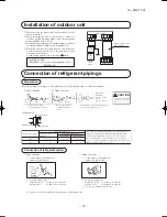
⑤
Blowing out port and suction port on the back side of the unit can
be installed at a distance of 10cm from walls.
In case the barrier is 1.2m or above in height, or is overhead, the
sufficient space between the unit and wall shall be secured.
⑥
When the unit is installed, the space of the following dimension
and above shall be secured.
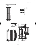
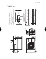
OUTDOOR UNIT
Note (1) If the wall is higher than 1.2 m or a ceiling
is present, distances larger than indicated in
the above table must be provided.
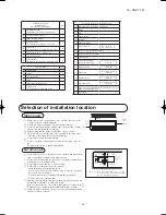
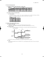
Selection of installation location
①
Where there is no obstructions to the air flow and where the
cooled air can be evenly distributed.
②
A solid place where the unit or the wall will not vibrate.
③
A place where there will be enough space for servicing. (Where
space mentioned right can be secured.)
④
Where wiring and the piping work will be easy to conduct.
⑤
The place where receiving part is not exposed to the direct rays
of the sun or the strong rays of the street lighting.
⑥
A place where it can be easily drained.
⑦
A place separated at least 1m away from the television or the ra-
dio.
(To prevent interfence to images and sounds.)
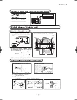
INDOOR UNIT
10 cm
5 cm
10 cm
Left
side
60 cm MIN
Air intake
10 cm MIN
10 cm
MIN
Air outlet
Air
intake
No obstacles
(Service space
for electrical
parts)
Right
side
(
)
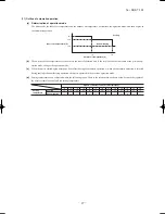
Standard accessories
(Installation kit)
Accessories for indoor unit
Q'ty
①
Installation board
(Attached to the rear of the indoor unit)
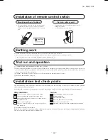
②
Wireless remote control
③
Remote control holder
④
Tapping screws
(for installation board dia. by mm)
⑤
Wood screw
(for remote contorol switch holder .dia. by mm)
⑥
Baterry [R0 (AAA, Micro) .V]
⑦
Air-cleaning filters
⑧
Filter holders
(Attached to the front panel of the indoor unit)
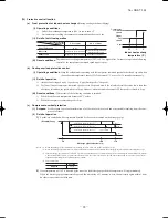
Necessary tools for the installation work
1
Plus headed driver (Phillips screwdriver)
2
Knife
3
Saw
4
Tape measure
5
Hammer
6
Spanner wrench
7
Torque wrench
( )
14.0 ~ 62.0N · m
(1.4 ~ 6.2kgf · m)
8
Hole core drill (mm in diameter)
9
Wrench key (Hexagon) [m/m]
10
Vacuum pump
11
Vacuum pump adapter
(Anti-reverse flow type)
( )
Designed specifically
for R410A
12
Gauge manifold
( )
Designed specifically
for R410A
13
Change hose
( )
Designed specifically
for R410A
14
Flaring tool set
( )
Designed specifically
for R410A
15
Gas leak detector
( )
Designed specifically
for R410A
16
Gauge for projection adjustment (Used when flare is made by
using conventional flare tool)
17
Pipe bender
Option parts
Q'ty
ⓐ
Sealing plate
ⓑ
Sleeve
ⓒ
Inclination plate
ⓓ
Putty
ⓔ
Drain hose (extention hose)
ⓕ
Piping cover
(for insulation of connection piping)
Содержание SRK18YLV-S1
Страница 2: ......
Страница 3: ...TECHNICAL MANUAL ...
Страница 9: ... 16 SRK T 192 3 Wireless remote control Unit mm 60 17 3 150 ...
Страница 53: ... 50 16 SRK T 192 ...
Страница 54: ... 51 16 SRK T 192 PARTS LIST INDOOR UNIT SRK18YLV S1 OUTDOOR UNIT SRC18YLV S1 ...
Страница 57: ... 54 16 SRK T 192 CRAE0254 21 17 23 24 22 18 1 8 5 7 6 3 2 4 15 9 11 12 16 19 13 14 20 25 10 HEAT EXCH CONTROL ...
Страница 59: ... 56 16 SRK T 192 CRBE0294 6 13 11 18 12 15 16 3 17 14 2 4 9 8 7 5 1 8 8 10 PANEL FAN ASSY ...


