


-
121
-
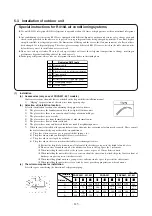
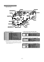
Power source and ground terminal block
Wiring clamp
™
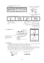
Secure the wiring so that no external force is applied to the
connecting portion of terminal.
Take out direction of wiring
™
Same as the refrigerant piping, 4 directions are allowed,
which are right, front, rear and down.
Wiring diagram
™
Wiring diagram is fixed at the backside of service panel.
Z
Y
X
Indoor unit
Remote
controller
SW1
M
Remote
controller
SW1
S
Z
Y
X
Z
Y
X
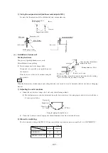
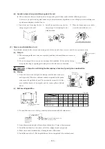
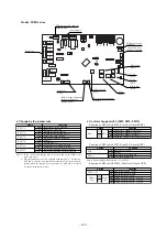
Remote control signal line (with polarity) (Match up X , Y and
Z when making connections.)
Upper
Lower
PCB
SW2
SW1
SW1
M
S
Switch
Function
M
S
Mastor remote controller
Slave remote controller
SW1
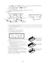
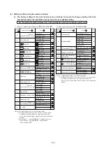
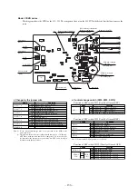
Indoor unit (1)
Address [0]
Red
White
Black
Remote controller
Z
Y
X
Z
Y
X
Indoor unit (2)
Address [1]
Z
Y
X
Indoor unit (16)
Address [F]
Z
Y
X
Remote control signal line (with polarity) (Match up X , Y and
Z when making connections.)
(c)
Remote controller wiring and connection procedure
1) Master-slave settings when using multiple remote controllers
●
Up to 2 remote controllers can be connected for each indoor unit (or group).
a) There are two methods, one where the remote controller signal line (3-wire) for the slave remote controller is taken
from the indoor unit and the other where the signal lines are taken from the master remote controller.
b) Set the SW1 select switch on the slave remote controller on the Slave setting. (It is set on the Master setting at the
factory.)
Note (1) Remote controller sensor activation settings are possible only with the master remote controller. Install the master remote controller in a
location where it can sense the room temperature.
2) Controlling multiple indoor units using a single remote controller.
●
Up to 16 indoor units can be controlled with a single remote controller.
a) Run 3-wire remote control lines between each of the indoor units. See “Cautions when extending remote control
lines” on page concerning extended remote control lines.
b) Set the remote controller communications address on “0” ~ “F” using rotary switch SW2 on the indoor unit’s
control board, taking care not to overlap the addresses of any of the units.
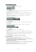
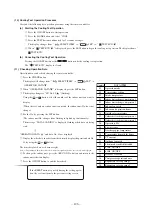
c) After turning the power on, press the AIR CON No. button to display the indoor unit’s address. Be sure to confirm
that the settings are displayed correctly in the remote controller by using the
and
buttons to display the
address of each connected indoor unit.


