


-
118
-
(c)
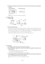
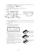
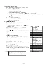
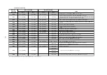
How to remove the service panel
First unscrew four screws holding the service panel in place, pull down the panel toward the direction indicated by the arrow,
and then pull it toward you to remove it from the casing.
Models FDCVA151~251
Models FDCA301~601
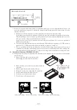
(d)
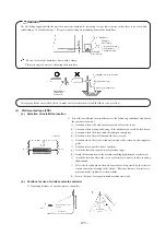
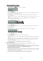
Refrigerant pipe connection
1) The pipe can be laid in any of the following directions: side right, front, rear and downward.
2) Remove a knock-out plate provided on the pipe penetration to open a minimum necessary area and attach an edging
material supplied as an accessory by cutting it to an approriate length before laying a pipe.
Models FDCA301~601
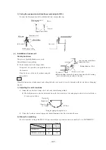
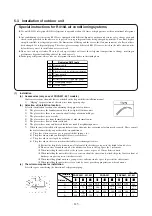
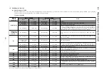
Airtighteness test completed
Vacuuming begins
Vacuuming completed
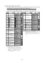
Vacuum gauge check
When the vacuum gauge's needle pointer creeps up, there is moisture left in the system
or a leak. Pull air again after you have checked the system for a leak and rectified it. Use
a reverse flow stop adapter to prevent the vacuum pump's lubricant oil from flowing into
the refrigerant system.
Please run the vacuum pump for at
least one hour after the vacuum gauge
shows -101kPa or lower. (-755mmHg
or lower)
No increase in the reading of the
vacuum gauge's needle pointer.
(4)
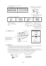
Air tightness test and air purge
●
Always use a vacuum pump to purge air trapped within an indoor and the refrigerant piping.
(a)
Air tightness test
1) When all the flare nuts on both indoor and outdoor unit sides are fastened. Conduct an air-tightness test from the service
valves (on both liquid and gas sides) closed tightly to check whether the system has no leaks.
2) Use nitrogen gas in the air-tightness test. Do not use gas other than nitrogen gas under any circumstances.
Conduct the air-tightness test by applying 4.15MPa (42kg/cm
3
G) of pressure.
3) Do not apply the specified pressure at once, but increase pressure gradually.
a) Raise the pressure to 0.5 MPa, and then stop. Leave it for five minutes to see if the pressure drops.
b) Then raise the pressure to 1.5 MPa, and stop. Leave it for five more minutes to see if the pressure drops.
c) Then raise the pressure to the specified level (4.15 MPa), and record the ambient temperature and the pressure.
d) If the pressure does not drop after the units is left for approximately one day, the airtighteness is acceptable.
When the ambient temperature changes 1˚C, the pressure also changes approximately 0.01 MPa. The pressure. if
changed, should be compensated for.
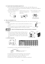
(b)
Air purge
Rear side connection
Right side connection
Service panel
Fixing screw
Screw for earth
Down side connection
Front side connection
When a vacuum air purge is completed, remove the valve rod cap nuts and open the service valves (both liquid and gas sides)
as illustrated below. After you have made sure that the valves are in the full-open position, lighten the cap nuts (for the valve
rads and charge ports).
Note (1) Piping can be run toward the back only of the FDCVA151~251 models.
Internal hook


