


-
105
-
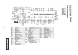
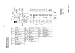
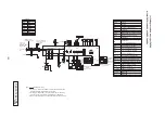
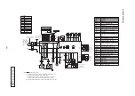
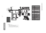
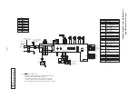
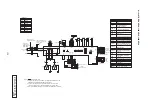
Models FDTW71KXE6, 90KXE6
B
P
JB
0
0
1
Z
5
6
1
WH
Y
Y
Connector for branching
controller of heat recovery
3−pipe systems
BK
BL
BR
GR
Black
Blue
Brown
Gray
OR
Orange
RD
Red
WH
White
Y
Yellow
Y/GN Yellow/Green
CNA
CNN
CNH
CNW2
1
2
t°
TB2
BL
RD
1
3
WH
BK
CNK1
CNB
XR1
XR2
XR3
XR4
1
2
3
4
5
6
+12
CNT
JSL1
(20S)
(SVH)
(SVG)
(SVE)
XB1
XB2
XB3
XB4
1
2
3
4
5
+12
CNT2
Control PCB
XR5(Remote operation input:
volt−free contact)
(Operation)
(Heating)
(Thermo ON)
(Inspection)
For Heat recovery
3−pipe systems
Superlink(spare)
Remote
controller
Earth
F(0.16A)
Option
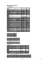
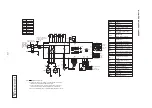
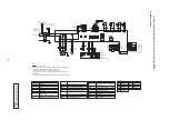
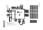
Color Marks
Mark
Color
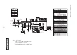
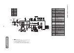
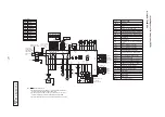
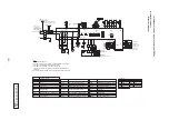
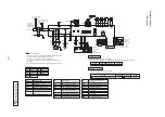
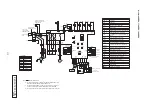
Notes 1. indicates wiring on site.
2. Use twin core cable(0.75〜1.25mm
2
)at signal line between indoor unit
and outdoor unit, and signal line between indoor units.
3. Use twin core cable(0.3mm
2
)at remote controller line. See spec sheet
of remote controller in case that the total length is more than 100m.
4. Do not put signal line and remote controller line alongside power source line.
Signal line(Shielded cord)
Signal line
between indoor units
I
I
I
I
I
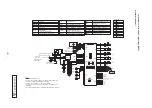
Relay for FM
Thermistor(Remote controller)
Thermistor(Heat exchanger )
Thermistor(Return air)
Model capacity setting
SW6
Thc
Th −R1,2,3
Th −A
X1〜3,6
Operation check, Drain motor test run
TB2
Terminal block(Signal line)(□mark)
Tr
SW7−1
Transformer
Relay for LM
Relay for DM
X4
X5
TB1
Terminal block(Power source)(□mark)
I
I
I
I
FS
CF
DM
FM
Float switch
Drain motor
Capacitor for FM
Fan motor(with thermostat)
I
F
Fuse
Connector
CNA〜Z
1
I
1
LS
LM
Louver switch
Louver motor
Indoor unit address: tens place
SW1
SM
Stepping motor
Indoor unit address: ones place
SW2
Indication lamp(Red−Inspection)
Indication lamp(Green−Normal operation)
LED・3
LED・2
SW3
SW4
Outdoor unit address: tens place
Outdoor unit address: ones place
SW5−1
Automatic adjustment/Fixed previous
SW5−2
Indoor unit address: hundreds place
Live Superlink terminal setting(for spare)
JSL1
version of Superlink protocol
(for electronic expansion valve)
CNJ
WH
CNF1
CF
LM
WH
BK
BL
CNS
X1
3
UH
WH
CNM3
C
WH
1
X6
M
H
BK
BL
5
7
L
RD
9
X3
X2
BK
LS
3
OR
CNJ2
CNR
3
BR
1
WH
WH
1
WH
X4
X5
CNI
BL
RD
RD
BL
WH
CNW1
CNS2
WH
BK
TB1
WH
RD
CNW0
WH
CNU
WH
RD
1
3
RD
RD
BL
CNR2
DM
BL
1〜
M
FS
M
1〜
1〜
M
BK
RD RD BR BR
1 2 3 4 5 6
RD
Th −R1
Th −A
Th −R2
BK
t°
t°
1
2
3
4
Th −R3
5
6
1
2
t°
GR
t°
M
WH Y OR BL BR RD
BK
BK
A B
X Y
X Y
WH
WH
BL
RD
SM
19V
24V
5
I
1
Thc
Power source
220ー240V〜 50Hz
Single−phase
line
Power source
between indoor units
Power source line
220ー240V
Tr
F(3.15A)
F(3.15A)
Y/GN
BK
BK
BK
BK
BK
GR
Y
BK
I
FM 1
BR
BK
Y/GN
LED・2
SW2
SW6
SW5
SW7
LED・3 SW1
SW3 SW4
CNK2
L
N
5 or 6 wires
Содержание 112KXE6
Страница 104: ... 100 3 ELECTRICAL WIRING 3 1 Outdoor unit Models FDC224KXE6 280KXE6 A PCB003Z033 shows local wining ...
Страница 105: ... 101 Model FDC335KXE6 A PCB003Z035 shows local wining ...
Страница 134: ... 130 PJF012D003 ...
Страница 135: ... 131 ...
Страница 139: ... 135 PJA012D751 b ...
Страница 140: ... 136 ...
Страница 206: ... 202 2 model type DIS model type HEAD ...
Страница 207: ... 203 2 2 ...
Страница 208: ... 204 2 2 2 2 2 ...


