- 1 -
Industrial Sewing Machine
XC-G500-Y
CONTROL PANEL Technical Information
(For Limi-Servo XC-G, XC-K Series)
Thank you for choosing the XC-G500-Y control panel. Please read this user manual carefully prior to usage.
Contents Page
1. HANDLING INSTRUCTIONS ·······························
2. INSTALLATION PROCEDURE ····························
3. SELECTION OF MODE ·······································
4. KEY NAMES AND FUNCTIONS ··························
5. OPERATION PROCEDURES ······························
Straight Lock Stitching ···························································
Backtacking
······································································
Continuous Backtacking
····················································
Using the Trimming Key
·····················································
Using the Automatic Key
····················································
Using the Needle Up Key
···················································
Using the Manual Stitching Key
··········································
Setting the Pattern by Teaching Input
··································
Setting the Pattern by Program Input
··································
Correcting the Data Programmed for Patterns A to H
············
Using the Continuous Key
·················································
Using the Function Key
·····················································
Using the Sensor Key
························································
Using the Program Keys
····················································
Settings Data Copy Function
··············································
6. ERROR DISPLAY ················································
1
1
2
2
5
5
5
6
6
7
7
7
8
9
10
11
12
12
13
13
13
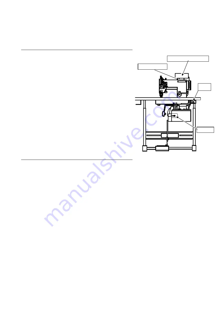
Fig. 1 Configuration
1. HANDLING INSTRUCTIONS
(1) Ensure to always connect the XC-G500-Y control panel to the Limi-Servo XC-G or XC-K Series control
box. The XC-G500-Y control panel cannot be used with other control boxes (XC-E, XC-F, XC-H Series
etc.).
(2) In the interests of safety, always turn OFF the power switch before inserting and removing the connector.
Please be aware that the control panel or control box may be damaged, and the memory contents may be
corrupted if the connector is inserted or removed with the power ON.
(3) Wipe off any machine oil adhering to the control panel with a soft cloth. There is a possibility of color
change, deformation, or peeling of the surface sheet if the control panel is left with oil adhering to it. Please
wipe with a neutral detergent if excessively dirty. Use of solvent will result in color change and deformation,
and therefore should not be used.
2. INSTALLATION PROCEDURE (See Fig. 1.)
(1) Turn OFF the power switch.
(2) Use the installation plate and screws provided, and install using the machine arm back plate tightening
screws and so forth.
(3) Exercise extreme caution to ensure lead wires do not come into contact with the rotating body like the
belt, pulley and so on.
(4) Connect the control panel connector firmly to the control box connector (see Fig. 1).
(5) The pattern display area are lighted when the power is turned ON.
E723D873-*(200512)
XC-G500-Y control panel
Installation plate
Connector
Power
switch


