


4-2
we are not showing the details of the DM circuitry.
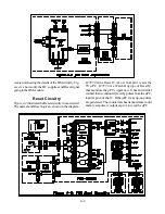
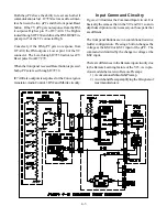
Fig-
ure 4-1
shows only the DC supplies and Reset signal
going to the DM module.
Reset Circuitry
Figure 4-2
illustrates the Reset circuitry in more detail.
The normal and Reset logic are shown in the diagram.
IC7C70 is the Reset IC. A Low from pin 1 resets the
TV µPC. IC7C70 is a Watch Dog type of Reset IC
that monitors the µPC’s operation. It has an internal
counter that is continually reset by pulses from the µPC,
input at pin 4 of the IC. If the µPC locks up, no pulses
are generated. The counter reaches its maximum count
and a reset pulse is output at pin 1 to reset the µPC.
Содержание WS-48513
Страница 2: ......
Страница 4: ......
Страница 17: ...11 Figure 13 V23 Chassis DVI Input Block Diagram ...
Страница 21: ...1 3 Figure 1 2 Main Chassis Removal Figure 1 3 DM Replacement Step 1 Step 2 Step 3 TOP VIEW REAR VIEW TOP VIEW ...
Страница 22: ...1 4 Figure 1 4 PCB Locations Figure 1 5 Main Component Locations ...
Страница 40: ...3 10 ...
Страница 70: ...8 2 Figure 8 2 Overall Sound Circuitry Block Diagram ...
Страница 72: ...8 4 ...
Страница 75: ......
Страница 76: ...Copyright 2003 Mitsubishi Digital ElectronicsAmerica Inc 9351 Jeronimo Road Irvine CA 92618 1904 T M V23 ...


