background image

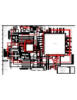
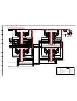
Analog_18V

BCKout

LRout

MUTE-SPKR1

I2SSDATA

I2SSCLKA

OUT1

I2SLRCKA

MASD

SD0out

MAWS

18V_SW

MASCK

A-GND

A-GND

A-GND

MUTE-SPKR2

SDAT-out

LRCK-out

DGND

DGND

DGND

SCLK-out

AUDADCLK

ADAC-RST2

_IN

SPKR_L-_IN

OUT2

AR-DSP

AL-DSP

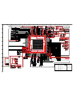
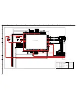
1

TST

3

SDI1

4

SDI0

5

LRI

6

VDDIO

7

BCKI

8

VSS

9

VDD

10 SDA2/TST

11 MUTEb

12 SCL2/WDC

13 PROC

14 VSSIO

15 VDDIO

16 SEL

17 VDDPLL

18 VSSPLL

19 VSS

20 VDD

2

TST

21 CLKOUT

22 CLK

23

VSSIO

24

VDDIO

25

RESETb

26

TST

27

TST

28

TST

29

AD1/SDIN

30

AD2/SSb

31

SCL/SCK

32

SDA/SDOUT

33

VDDIO

34

MCK

35

BCKO

36

LRO

37

TST

38

TST

39

SDO1

40

SDO0

41

VDDIO

42

VSSIO

43

VSS

44

VDD

1

2

3

4

5

6

7

8

9

10

11

12

13

14

15

16

1

2

3

4

5

6

7

8

9

10

11

12

13

14

15

16

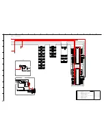
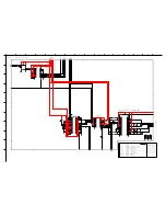
1

VSSD(HW)

3

IN1N

4

DIAG

5

ENGAGE

6

POWERUP

7

CGND

8

VDDA

9

VSSA

10 OSCREF

11 HVPREF

12 INREF

13 TEST

14 IN2N

2

IN1P

15 IN2P

16 VSS(HW)

17

VSSD(HW)

18

DREF

19

HVP2

20

VDDP2

21

BOOT2

22

OUT2

23

VSSP2

24

STAB2

25

STAB1

26

VSSP1

27

OUT1

28

BOOT1

29

VDDP1

30

HVP1

31

OSCIO

32

VSSD(HW)

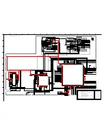
MMZ1608S601A

MMZ1608S601A

MMZ1608S601A

MMZ1608S601A

MMZ1608S601A

MMZ1608S601A

MMZ1608S601A

MPZ2012S221A

3.3V_3

9VSA_3

1.8VS-DM

1.8VS-DM

5VS-A

21VA

ADC3.3VS

3.3VS

3.3VS

9VS

9VS

A-GND

MAIN-R

ADAC-RST2

MAIN-L

10K

R3P07

10K
1/16W

R3D23

0.1

C3E41

16V

K-0.33M

C3E64

25V

2.2U

C3E33

6.3V

100

1/16W

R3A10

0.1

C3P05

25V/16V

1/16W

R3D28

560

0.1

C3P29

SPKR(L-)

DGND

0.015

C3E51

50V

3.3K

1/16W

R3P08

MUTE-SPKR1

2.2U

C3E37

6.3V

DGND

DGND

AUDIODSP-RST

R3P35

47

10K

1/16W

R3E32

0.1

C3E48

25V/16V

1500

C3E75

50V

K-0.33M

C3E68

25V

K-4.7M

C3A02

B6.3V

820

1/16W

R3A02

R3P34

47

10K

1/16W

R3E36

1/16W

R3A21

33

0.1

C3E42

25V/16V

0.1

C3P32

SPKR(L+)

2SC3052-T112-1E,F

Q3A01

1500

C3E73

50V

1/16W

R3D21

100

DGND

0.1

C3E44

25V/16V

I2SSDATA

470

C3E53

50V

47

R3P47

820

1/16W

R3A07

C3A14

2.2U
6.3V

RT1N436C-T112-1

Q3E01

1/16W

R3E35

4.7K

1/16W

R3A06
100

1500

C3E77

50V

0.1

C3E63

25V/16V

R3P27

100

0.1

C3P11

25V/16V

0.1

C3A16

25V/16V

L3E05

22uH, 3A

SPKR(R-)

0.1

C3D24

25V/16V

47

R3P02

MASCK

I2SSCLKA

DGND

1/16W

R3A22

33

1/16W

R3A04

47

0.1

C3E60

50V/25V

1/16W

R3E24

0

0.1

C3P20

10

1/4W

R3E43

K-0.33M

C3E10

25V

R3P39

47

0.1

C3E55

25V/16V

1/16W

R3D29

560

1/16W

R3A09

47

DGND

0.015

C3E58

50V

SPKR(R+)

DGND

2.2U

C3E31

6.3V

DGND

MAWS

820

1/16W

R3A03

0.1

C3A01

25V/16V

I2SMCLKA

22
1/4W

R3E44

0.1

C3E50

50V/25V

0.1

C3E40

50V/25V

0.1

C3P16

25V/16V

0.1

C3P13

25V/16V

2.2U

C3E35

6.3V

10K

1/16W

R3A14

K-0.33M

C3E12

25V

K-4.7M

C3A05

B6.3V

1/16W

R3E39

39K

0.1

C3P01

25V/16V

0.1

C3E49

25V/16V

I2CCLKB

1500

C3E71

50V

2SC3052-T112-1E,F

Q3A02

1/16W

R3E06

22K

1/16W

R3E31

4.7K

MASD

22
1/4W

R3E47

DGND

I2SLRCKA

470

C3E56

50V

1/4W

R3E30

10

1500

C3E74

50V

10K

1/16W

R3D22

0.1

C3E29

50V/25V

47

R3P48

DGND

1/16W

R3A13
10K

1500

C3E76

50V

0.1

C3A17

25V/16V

I2CDATB

DGND

10
1/4W

R3E46

0.1

C3D21

25V/16V

DGND

AUDADCLK

1/16W

R3E37

4.7K

0
1/16W

R3E25

1/16W

R3A23

33

A-GND

3.3K
1/16W

R3P51

2200

C3D29

50V

A-GND

DGND

0.1

C3P21

0.1

C3E67

25V/16V

DGND

0.1

C3P31

820
1/16W

R3A08

1/16W

R3A01
100

DGND

1500

C3E70

50V

L3E04

22uH, 3A

1/16W

R3E33

4.7K

2200

C3D28

50V

R3P28

100

0.1

C3E61

25V/16V

1500

C3E72

50V

MUTE-SPKR2

100
1/16W

R3D02

100

1/16W

R3D01

AR-DSP

AL-DSP

.33M

C3E15

16V

6.3V

C3A15

22

6.3V

C3A18

22

6.3V

C3D22

22

6.3V

C3D23

22

16V

C3D25

22

35V

C3E28

22

16V

C3E43

100

6.3V

C3P12

22

27

C3P17

50V

27

C3P18

50V

270

R3P17

DGND

L3D09

L3D08

L3P03

L3P02

L3P01

L3A02

L3A03

L3E02

X3P01

12.288MHz

25V

C3E65

1000U

25V

C3E69

1000U

C3E26

470U
35V

C3E27

470U
35V

12.288MHz

Mast_CLK

CLK

L/R_CLK

Rmain/2

Lmain/2

DATA

PWR_ON/OFF

MUTE

21V

21V

IC3P01

NJU26204V-TE2

AK4341ETP

PLD

Sys.clk.

gen.

3.3VS

5VS

9VS

1.8VS-DM

IC3A01

AK5358AETP

AINR

AINL

CKS1

VCOM

AGND

VA

VD

DGND

SDTO

LRCK

MCLK

SCLK

PDN

DIF

CKS2

CKS0

IC3D03

MCLK

BICK

SDTI

LRCK

PDN

SMUTE

ACKS

DIF

DEM

AOUTR

AOUTL

HVDD

VSS

VDD

VCOM

GAIN

21VA

TDA8932BTW/N2

IC3E02

SPKR_L-

5

ES

SHT.1

 MAIN 2

MAIN 12

MAIN 12

MAIN 4

SPKR_R-

MAIN 6

MAIN 1

MAIN 5

PWR

MAIN 4

I2S_A

MAIN 1

MAIN 4

1

2

4

MAIN 4

MAIN 2

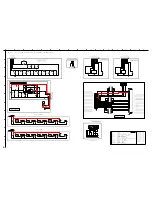
[CONT/PREAMP/SBL/FRONT/HDMI/SW-LAMP/LED]

AUDIO ADC

SPKR L/R

 SPEAKERS

DSP

DAC

PG 12....MAIN10 [TMDS]

PG 7.....MAIN5 [DM-MEMORY]

PG 8.....MAIN6 [DM-ROM / AV]

PG 5.....MAIN3 [HDMI / SYSTEM5]

WD-65835 V39++

WD-63736 V39+

CONTENTS

PG 1.....BLOCK

WD-60735 V39

PG 10....MAIN8 [SPA3 MAIN]

PG 6.....MAIN4 [DM-CORE]

WD-65735 V39

PG 13....MAIN11 [AUDIO]

PG 9.....MAIN7 [ANALOG-DIGITAL CONVERTOR]

WD-73735 V39

PG 3.....MAIN1 [DC-DC / IF]

WD-73835 V39++

WD-73C8  V39C

PG 11....MAIN9 [SPA3 MEMORY]

PAGE 13

WD-73736 V39+

PG 15....MISC

PG 4.....MAIN2 [AV-SWITCH / TUNER]

PG 14....MAIN12 [MICRO]

PG 2.....POWER

WD-60C8  V39C

WD-65C8  V39C

L

2X10W CLASS-D POWER AMP.

R

5

11

15

13

3

9

8

7

16

2

6

10

12

1

14

4

C

F

E

A

H

K

J

B

G

D

I

PG 13....MAIN11 [AUDIO]

Содержание WD-60735

Страница 1: ...RST 75Ω unbalanced COMP Y Cr Cb RCAType Y 1 0 Vp p Cr Cb 700mVp p Output Level AUDIO OUT JACK RCAType 4 7dBm 4 7kΩ unbalanced Digital AC 3 Digital Audio Output RCAType HDMITM IR Blaster Output V39 V39 only USB PC use HMDITM Wired IR Input V39 V39 only WD 52327 V39 Chassis WD 60735 WD 65735 WD 73735 WD 52527 Pb Solder V39 Chassis WD 65736 WD 73736 V39 Chassis WD 60C8 WD 65C8 WD 73C8 V39 Chassis WD ...

Страница 2: ......

Страница 3: ...placement 13 Ballast Removal 14 SCREEN DISASSEMBLY 14 WD 65835 WD 73835 Escutcheon Removal 14 Screen Assembly Bezel Removal 14 Screen Removal From Bezel 16 Screen Replacement 18 SPEAKER PWB SBL Replacement 19 Speaker Replacement 19 INITIALSETTINGS INITIALIZATION TROUBLESHOOTING 20 Option Menu Remote Control 20 Digital Signal Strength 20 Reset and Initialization 21 Initial Settings 22 A V Reset 23 ...

Страница 4: ...wer Supply 47 DC to DC Supplies 48 Analog Video Signal Path 49 Digital Video Signal Path 50 Overall Sound Signal Path 51 Overall Control Circuitry 52 Auto Input Output Detect Circuitry 53 Lamp Control Circuitry 54 Short Detect Circuitry 55 Engine Protect Circuitry 55 System 5 Wired Remote I O 56 SCHEMATIC DIAGRAMS Digital Light Processing Digital Micro Mirror Device and DLP are Trademarks of Texas...

Страница 5: ...OTICE Many electrical and mechanical parts in television receivers have special safety related characteristics These charac teristics are often not evident from visual inspection nor can the protection afforded by them necessarily be obtained by using replacement components rated for higher voltage wattage etc Replacement parts which have special safety characteristics are identified in this servi...

Страница 6: ...plug removed from the AC source place a jumper across the two AC plug prongs Connect one lead of an ohm meter to the AC plug and touch the other lead to each exposed metal part i e antennas handle bracket metal cabinet screw heads metal overlay control shafts etc particularly any exposed metal part that has a return path to the chassis The resistance of the exposed metal parts having a return path...

Страница 7: ...e 1 Remove the Lamp Cover 2 Remove screws A from the back cover 3 Pull the back cover from the TV Back Cover Installation Reverse the removal procedure but install the Lamp Cover Last Chassis Removal Chassis Removal 1 Remove four screws A 2 Disconnect all cables connecting to the chassis 3 Carefully slide the chassis out of the Cabinet DISASSEMBLY ...

Страница 8: ... RF inputs 2 Remove screws A that secure the cover to the chassis 3 Pull the Inputs Cover from the chassis PWB POWER Removal 1 Remove five screws B 2 Disconnect all cables to the PWB POWER 3 Release clips C 4 Carefully lift the PWB POWER from the chassis box PWB POWER Installation 1 Reverse the removal procedure to install a new PWB POWER 2 No data transfer is required DO NOT use a power driver on...

Страница 9: ...tinued Chassis Cover Removal 1 Remove 3 screws C 2 Lift the Chassis Cover from the chassis box PWB HDMI FRONT Removal 1 Disconnect all cables to PWB HDMI FRONT 2 Remove three screws D 3 Carefully lift the PWB HDMI FRONT from the chassis box 4 To remove PWB HDMI remove two screws E and slide the PWB out the rear of the shield ...

Страница 10: ...ect all cables to PWB MAIN 2 Remove two screws D 3 Remove screws E 4 Carefully lift the PWB MAIN from the chassis box PWB MAIN Installation 1 Install two screws D first 2 Then install screws E 3 Transfer Index Data from Engine refer to page 32 4 Restore Alignment and White Balance Settings 5 Restore Keystone Geometry from Backup ...

Страница 11: ...D 73C8 Page 11 OPTICAL ENGINE REMOVAL OPTICAL ENGINE ASSEMBLY REMOVAL 1 Remove 3 screws C from the Optical Engine 2 Disconnect all cables to the Optical Engine Assembly 3 Carefully slide the Optical Engine assembly from the cabinet OPTICAL ENGINE ASSEMBLY AND CONNECTOR LOCATIONS Rear View ...

Страница 12: ...nnector locations 1 Loosen two screws a to remove the Lamp Cartridge refer to Figure 1 3 Remove 3 screws b from the top of the upper duct and release the 7 snaps shown in Figure 2 4 Carefully remove the upper Duct assembly LOWER DUCT Upper Duct Removed 1 Figure 3 shows the components in the Lower Duct 2 The Sirocco Fan and Exhaust Fan can be replaced The Engine and Upper Duct do not have to be rem...

Страница 13: ...uct refer to Figures 4 and 5 2 Carefully remove the lower duct from the Engine ENGINE REPLACEMENT Reverse the Removal Procedure 1 Install Duct assembly on the new Engine 2 Remove the Protective Lens Cover from the face of the Lens 3 Install the Engine Assembly in the cabinet 4 After a new Engine is installed Load Index Delay Data from the Engine and Copy Settings to Backup page 32 5 Adjust Raster ...

Страница 14: ...move screw D to remove the PWB BALLAST from the Ballast Support Reverse the procedure to install a new Ballast SCREEN REMOVAL REPLACEMENT Screen Assembly Bezel Removal 1 Remove all rear screws B except one in an upper corner To support the screen assembly while removing the front mounting screws 60 Inch Models WD 65835 WD 73835 Only Escutcheon Removal Before Removing the Screen Assembly V39 Models...

Страница 15: ...MODELS WD 60735 WD 60C8 WD 65735 WD 65736 WD 65835 WD 65C8 WD 73735 WD 73736 WD 73835 WD 73C8 Page 15 65 inch Models SCREEN REPLACEMENT continued 73 inch Models ...

Страница 16: ...bly Removal continued 2 Open the Control Panel door and remove two screws A 3 Remove the remaining rear screw in the upper corner and carefully pull the screen assembly from the cabinet Screen Removal From the BEZEL FRONT 1 Remove the screws A from the top bottom and side rails 2 Lift the Fresnel Lens and Lenticular screen from the BEZEL FRONT ...

Страница 17: ...MODELS WD 60735 WD 60C8 WD 65735 WD 65736 WD 65835 WD 65C8 WD 73735 WD 73736 WD 73835 WD 73C8 Page 17 SCREEN REPLACEMENT continued ...

Страница 18: ...long the top edge 3 Place the screens in the screen frame and reinstall the cushions top bottom and side rails NOTE The Lenticular Screen label must face the front and the Fresnel Lens label face the rear 4 Reverse the Screen Removal Procedure and insert the screens in the Bezel Lenticular Screen and Fresnel Lens Removal 1 Remove the top bottom and side HOLDER SCREEN rails and their cushions from ...

Страница 19: ...4 Remove 4 screws B to remove the speaker from the speaker cover 5 Reverse the procedure to install a replacement speaker WD 65835 WD 73835 Only PWB SBL R PWB SBL L Replacement 1 The screen Bezel Assembly must be removed to access the PWBs SBL refer to the V38 Bezel Removal Procedure 2 Remove 2 screws A to remove the PWB SBL assembly from the Bezel 3 Remove 4 screws B to remove the PWB from the as...

Страница 20: ...l Channel 2 From the Option menu scroll down and highlight Digital Signal Strength 3 Press Enter SNRRecommendedLevels VSB 15 to 35 64 QAM 22 to 34 256 QAM 27 to 37 Example of Digital Signal Strength Display Signal Quality Index 0 100 Signal Noise Ratio Tuner 0 Tuner 1 OOB Tuner Frequency MHz 597 0 0 Signal Level 8 0 0 Modulation 256 QAM Unknown Unknown Carrier Lock Locked Unknown Unknown SQI 100 0...

Страница 21: ...P The remote will now operate the TV s volume and mute when the slide switch is in the TV CABLE SAT VCR or DVD positions A V Memory Reset by individual input When the audio and or video settings for a single input seems to be incorrect All Audio and Video settings for the individual input are reset except for the Listen To Language Balance and Closed Caption settings A V Reset all inputs To reset ...

Страница 22: ...Energy Mode Fast power on PerfectColor On Lamp Mode Standard PerfecTint Other Ratings Gray out Global Medium Other ratings Off Video Mute On Inputs Menu Standard Film Mode Auto Name SharpEdge V39 On Ant 1 On Lamp Mode Standard Ant 2 On Blue Glow V39 only On if TV On Input 1 Gray out FX Gaming Gray out Input 2 Gray out Game Mode Off Input 3 Front Gray out Glasses L R Standard Comp 1 Gray out Captio...

Страница 23: ...ant Bright Bright Brilliant Contrast MAX MAX MAX MAX MAX MAX MAX Brightness Center Center Center Center Center Center Center Color Center Center Center Center Center Center Center Tint Center Center Center Center Center Center Center Sharpness Center Center Center Center Center Center Center Color Temp High High High High High High High Perfect Color Center Center Center Center Center Center Cente...

Страница 24: ...iagnostics The front panel LEDs provide an indication of the set s operation and the possible cause of a malfunction There are three front panel LEDs Power Status and Lamp The LED display shows the current status or indicates a possible malfunction Pow er Timer LED Status LED Lamp LED Condition Off Yellow Off Temperature high room too hot Temperature sensor is disconnected Off Off Blinking Yellow ...

Страница 25: ...nation of a defective part Code Description Most Likely Cause 12 No Error found 17 Communication loss TV Micro Engine 3 3V ENG SDA SCL Engine Failure Loss of 12V from PWB POWER Loose 18 Engine will not accept data ASIC READY signal from Engine is not PE or PE2 connector Bad Color Wheel detected Loose J6 or J7 connector Engine Failure 32 Lamp cover is open Lamp Cover Switch Loose CD connector Lamp ...

Страница 26: ...ure CW1 4 Disconnect the 2 connectors B as shown in picture CW1 J6 J7 in CW2 5 Lift the top cover to the color wheel chamber Symptoms Noise Bad Motor Bearing Solarized Picture Before replacing the Color Wheel try adjusting the IDL Index Delay refer to page 27 forthealignmentprocedure Replacement Procedure CAUTION This procedure should be done in a dust free environment Any dust entering into the c...

Страница 27: ...ust IDL value until RAMP pattern color bars are smooth and solid Hint Finalvalueistypicallyinthemid30 s 6 Remove 3 screws C as shown in picture CW3 7 Hold the color wheel by the handle and pull it from the chamber 8 Install the new color wheel and reverse the above procedure making sure to not scratch the wheelorallowdustinsidethechamber CAUTION Do not twist the ribbon cable to J6 the shiny silver...

Страница 28: ...Mode is used for Test Signal activation Horizontal and Vertical Centering Manual alignment of keystone geometry The following adjustments may only be performed using the remote control Horizontal and Vertical Centering Adjustment 1 Activating the Adjustment Mode 1 Press the MENU button on a remote hand unit The MENU display will appear 2 Press the buttons 2 4 5 and 7 in that order Adjustment mode ...

Страница 29: ...etry When the adjustment mode is activated all 16 points will be set to default position The adjustment is not saved until the ENTER button has been pressed Pressing the ENTER button will save however it will not indicate this in any manner For the adjustment to work properly all 16 points must be aligned before pressing the ENTER button 1 Activating the Adjustment Mode 1 Press the MENU button on ...

Страница 30: ...e DIRECTION bcef buttons to align the selected point cross cursor with the Bezel edge 3 Use the FAST FORWARD ff button to move between each point or REWIND ee to go back 4 Align each point in a straight line use the Bezel as a reference See example drawing in Figure 1 NOTE Only the cross will move the pattern will not change 5 After all 16 points are aligned properly pressing the ff button and the...

Страница 31: ...ns Select the pattern with the straightest blue vertical lines that are parallel to the Bezel edge 10 Press VIDEO to activate the Top Letter Box alignment mode refer to Figure 3 11 Use the ff or ee buttons to step through 15 preset alignment settings Select the setting with the straightest top letter box line red line that is parallel to the Bezel edge Continued on the following page Figure 3 Top ...

Страница 32: ...ent 2 Load Index Delay from Engine 4 3 MODE Select Straightest Red Line Bottom Figure 4 Bottom Letter Box Mode Pattern 12 Press VIDEO to activate the Bottom Letter Box alignment mode refer to Figure 4 13 Use the ff or ee buttons to step through 10 preset alignment settings Pick the setting with straightest bottom letter box line that is parallel to the Bezel edge 14 Press ENTER to save and exit th...

Страница 33: ...r temperatures can cause surface oxidation resulting in poor solder spread ability and wet ability The flux is more corrosive The time required for a good solder connection may take longer Poor wet ability can cause solder balls Higher temperatures can cause flux spattering Soldering iron tip life is shortened Dull finish solder joints not shiny can appear to be a cold solder joint In general a ti...

Страница 34: ...nd remove the chip parts carefully so as not to tear the copper foil from the printed circuit board 3 Discard removed chips do not reuse them 4 Do not apply heat for more than 3 three seconds to new chip parts 5 Avoid using a rubbing stroke when soldering 6 Take care not to scratch or damage the chip parts when soldering 7 Supplementary cementing is not required Chip Parts Removal Resistors Capaci...

Страница 35: ...of orders will result Critical and Warranty Parts Designation Critical Electrical Components are indicated by Bold Type and a icon in the Parts List and in the schematic diagrams by a red hatch and a Parts Tolerance Codes Refer to the following chart for tolerance characteristics of electrical components MARK B C D F G J K Tolerance 0 1 0 25 0 5 1 2 5 10 MARK M N V X Z P Q Tolerance 20 30 10 40 80...

Страница 36: ... WD 60C8 WD 65735 WD 65736 934C282002 935D984002 WD 65835 934C282003 935D982002 WD 65C8 934C282001 935D982001 935D984001 WD 73735 WD 73736 934C282002 935D984002 WD 73835 934C282003 935D982002 WD 73C8 934C282001 935D982001 935D984001 PRINTED CIRCUIT BOARDS MODEL OPTICAL ENGINE FRESNEL LENS LENTICULAR SCREEN MIRROR KIT REMOTE WD 60735 938P126040 491P2180010 491P217010 KIT MIR 767D086010 291P137010 W...

Страница 37: ... MOS PL671 33 120SC R IC9A10 267P175030 HIC STR W6734 IC9A20 271P142010 IC RT9H301C IC9C51 271P251020 IC MM1663DHBE IC9G01 271P253010 IC AOZ1010AI IC9G02 271P254010 IC ISL6545ACBZ TS2698 IC9G03 271P254010 IC ISL6545ACBZ TS2698 IC9G05 271P272010 IC NJM2386ADL3 09 IC9G80 271P171010 IC MIC2040 1YMM CHIPType Transistors Listed by Part No Part No Description 261P842080 2SC3052 T112 1E F 261P844010 RT1N...

Страница 38: ...dehi L2002 409P974010 CHIP BEADS MMZ1608S601A L2003 409P974010 CHIP BEADS MMZ1608S601A L2004 409P974010 CHIP BEADS MMZ1608S601A L2005 409P974010 CHIP BEADS MMZ1608S601A L2006 409P974010 CHIP BEADS MMZ1608S601A L2007 409P974010 CHIP BEADS MMZ1608S601A L2008 409P974010 CHIP BEADS MMZ1608S601A L2009 409P974010 CHIP BEADS MMZ1608S601A L2101 409P974010 CHIP BEADS MMZ1608S601A L2102 409P974010 CHIP BEAD...

Страница 39: ...961010 CHIP FILT ACM2012D 9002P T7C54 409P961010 CHIP FILT ACM2012D 9002P T7C57 409P961010 CHIP FILT ACM2012D 9002P T7C60 409P961010 CHIP FILT ACM2012D 9002P TRANSFORMERS T9A10 350P853010 TRANS POWER SRW2630EG U01V016 VARIABLERESISTORS RV9D00 265P100040 VARISTOR ERZV10D471CS RV9D01 265P100040 VARISTOR ERZV10D471CS CHIPRESISTORS byvalue CHIP Type Resistors Listed by Value Part No Value Part No Valu...

Страница 40: ...81P822030 16V 10M M 105C 141P141010 B50V1500P K 181P826050 50V 10M M 105C 141P141030 B50V2200P K 189P253020 B16V10M M 141P141060 B50V3900P K 189P253010 B6 3V 10M M 141P142000 B50V8200P K 181P822040 16V 22M M 105C 141P142010 B50V0 01M K 181P825010 35V 22M M 105C 141P143080 F50V 0 01M Z 181P820010 6 3V 22M M 105C 141P132030 B50V0 015M K 181P822060 16V 47M M 105C 141P142050 B25V0 022M K 181P820030 6 ...

Страница 41: ...E ZCAT3513S Fans 299P335010 COOLING FAN D34902 57MDEA1 299P321010 FAN SCIROCCO BG0703 B042 00L T3 299P339010 FAN DMD OpticalEngines 938P126040 OPTICAL ENGINE 60 ab 938P126050 OPTICAL ENGINE 65 cdf 938P126060 OPTICAL ENGINE 73 ghj 955B378001 OPTICAL ENGINE 65 e 955B378002 OPTICAL ENGINE 73 i PhotoCouplers PC9A10 268P125010 PHOTO COUPLER FOD617C PC9A20 268P125010 PHOTO COUPLER FOD617C Quartz Crystal...

Страница 42: ...ROR 73 KIT MIR767D086010 MIRROR 60 KIT MIR767D086020 MIRROR 65 771D127030 PAD BOTTOMFEET 771D139010 PAD BOTTOMFEET 771D139020 PAD MIRROR HOLDER COSMETICPARTS 716C044010 BADGE BRAND abcdfghj 716C047010 BADGE DIAMOND ei 716C053010 BADGE BRAND ei 760C798010 INLAY FRONT CONTROL e 760C799040 INLAY FRONT INPUT e 760C803010 INLAY FRONT CONTROL i 760C804030 INLAY FRONT INPUT i 760C806010 INLAY LED RIGHT i...

Страница 43: ...B cdf 4 593B359010 HOLDER SCREEN B ab 4 593B372010 HOLDER SCREEN B ghj 5 621B184020 HOLDER SCREEN S e 5 621B196010 HOLDER SCREENS ab 5 621B196020 HOLDER SCREENS cdf 5 621B207010 HOLDER SCREEN S ghj SCREENPARTS Ref Part Description Model 6 622C487080 SPACER abcdfghj 7 622C487030 SPACER BEZEL CUSHION3 ei 8 622C487050 SPACER BEZEL CUSHION2 e 9 622C487060 SPACER BEZEL CUSHION1 ei 10 621B208020 COVER H...

Страница 44: ...ER 43 5 16 in TOP 601D001040 STIFFENER 33 1 2 in SIDE 601D001050 COVER HOLDER MIRROR 623D439030 HOLDER MIRROR EDGE SIDE BTM 623D439040 WD 65735 WD 65736 WD 65C8 WD 65835 KIT MIR WD65835 WD 73C8 WD 73735 WD 73736 WD 73835 KIT MIR 767D086010 KIT MIR 767D086020 KIT MIR WD73735 WD 60C8 WD 60735 Side Stiffener Top Stiffener 65 Models 1 6 in 40mm SIDE Edge N A WD 65835 1 6 in 40mm SIDE Edge 2 4 in 60mm ...

Страница 45: ... Page 45 Back Side of Mirror Mirror 2 Install HOLDER MIRROR EDGE to both side edges and the bottom of the mirror 2 3 8 in Date Code STIFFENER SIDE STIFFENER TOP Example of 65 1 9 16 in WD 65835 Only COVER HOLDER MIRROR Back Side of Mirror Date Code 5 7 8 in 7 7 8 in 5 7 8 in Example of 73 2 in ...

Страница 46: ...Install COVER HOLDER MIRROR to top of mirror 73 models only Mirror 5 73 V39 Models Install HOLDER MIRROR TOP HOLDER MIRROR TOPwill fit into the groove of the COVER HOLDER MIRROR 65 Models Install BRACKET MIRROR to bottom left and right corners COVER HOLDER MIRROR 73 only HOLDER MIRROR SIDES HOLDER MIRROR TOP V39 73 MIRROR BOX Figure M6 Front of Mirror COVER HOLDER MIRROR Back of Mirror Top of Mirr...

Страница 47: ...Page 47 MODELS WD 60735 WD 60C8 WD 65735 WD 65736 WD 65835 WD 65C8 WD 73735 WD 73736 WD 73835 WD 73C8 MAIN POWER SUPPLY ...

Страница 48: ...Page 48 MODELS WD 60735 WD 60C8 WD 65735 WD 65736 WD 65835 WD 65C8 WD 73735 WD 73736 WD 73835 WD 73C8 DC DC Supplies ...

Страница 49: ...Page 49 MODELS WD 60735 WD 60C8 WD 65735 WD 65736 WD 65835 WD 65C8 WD 73735 WD 73736 WD 73835 WD 73C8 ANALOG VIDEO SIGNAL PATH ...

Страница 50: ...Page 50 MODELS WD 60735 WD 60C8 WD 65735 WD 65736 WD 65835 WD 65C8 WD 73735 WD 73736 WD 73835 WD 73C8 DIGITAL VIDEO SIGNAL PATH ...

Страница 51: ...Page 51 MODELS WD 60735 WD 60C8 WD 65735 WD 65736 WD 65835 WD 65C8 WD 73735 WD 73736 WD 73835 WD 73C8 SOUND SIGNAL PATH ...

Страница 52: ...Page 52 MODELS WD 60735 WD 60C8 WD 65735 WD 65736 WD 65835 WD 65C8 WD 73735 WD 73736 WD 73835 WD 73C8 OVERALL CONTROL CIRCUIT ...

Страница 53: ...Page 53 MODELS WD 60735 WD 60C8 WD 65735 WD 65736 WD 65835 WD 65C8 WD 73735 WD 73736 WD 73835 WD 73C8 INPUT OUTPUT AUTO DETECT ...

Страница 54: ...Page 54 MODELS WD 60735 WD 60C8 WD 65735 WD 65736 WD 65835 WD 65C8 WD 73735 WD 73736 WD 73835 WD 73C8 Lamp Control Circuitry LAMP CONTROL CIRCUITRY ...

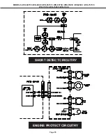
Страница 55: ...Page 55 MODELS WD 60735 WD 60C8 WD 65735 WD 65736 WD 65835 WD 65C8 WD 73735 WD 73736 WD 73835 WD 73C8 ENGINE PROTECT CIRCUITRY SHORT DETECT CIRCUITRY ...

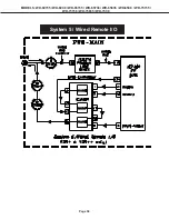
Страница 56: ...Page 56 MODELS WD 60735 WD 60C8 WD 65735 WD 65736 WD 65835 WD 65C8 WD 73735 WD 73736 WD 73835 WD 73C8 System 5 Wired Remote I O ...

Страница 57: ...IN6 DM ROM AV PG 10 MAIN8 SPA3 MAIN WD 73835 V39 PG 4 MAIN2 AV SWITCH TUNER WD 65835 V39 WD 65735 V39 WD 73C8 V39C PG 14 MAIN12 MICRO WD 63736 V39 PG 13 MAIN11 AUDIO PAGE 1 PG 2 POWER CONTENTS PG 9 MAIN7 ANALOG DIGITAL CONVERTOR PG 15 MISC PG 5 MAIN3 HDMI SYSTEM5 PG 6 MAIN4 DM CORE PG 11 MAIN9 SPA3 MEMORY PG 7 MAIN5 DM MEMORY WD 60735 V39 PG 3 MAIN1 DC DC IF WD 60C8 V39C WD 65C8 V39C DLP ENGINE PW...

Страница 58: ...6V 0 1 C9A24 16V 0 22 C9D00 AC125V 250V 3300P J C9A70 630V 0 047 C9A43 16V 25V MTZJ6 2C LF D9A22 MTZJ6 2C LF D9A03 31DQ09 FC5 D9A31 1S2076A 1S2471OM D9A20 11EFS2N TA2B5 D9A24 11EFS2N TA2B5 D9A23 1S2076A 1S2471OM D9A02 D9A18 D9A19 SARS01 D9A05 1S2076A 1S2471OM D9A04 11EFS2N TA2B5 D9A25 1 2 3 AG9D00 DE37 452M A21F D9A26 FCHS10A065 15A D9A00 D3SB80 7001 1 2 3 4 PL IC9A20 RT9H301C PD PE RV9D01 RV9D00 ...

Страница 59: ... MANRST 0 1 C9G71 25V 16V PWRLED LAMPEN BALLAST RT1N436C T112 1 Q9G10 16V C9G19 100 4 5 6 7 1 2 3 1 16W R9G23 22 10K 1 16W R9G27 0 1 C9G73 25V 16V 10 4 5 6 7 8 9 1 2 3 DGND A GND 4 1 2 3 0 1 C9G80 25V 16V DGND DGND DGND STEREO SYNC DGND 3 3V ENG SDA 3 3V ENG SCL RDB TXDB BUS REQ DGND 10 4 5 6 7 8 9 1 2 3 TP1 2VS TP3 3V TP3 3VS TP3 3VSL TP5VS 0 1 C9C55 25V 16V 1 16W R9G14 100K 33M C9C51 16V 0 1 C9G...

Страница 60: ... 2 2U C3F23 6 3V DGND R2J66 75 R2J65 75 I2CDATC 1 16W R104 2 2K 0 1 C2J34 25V 16V K 4 7M C3F22 B6 3V R2J03 75 1 16W R2J42 100 R2J63 120K AVR L TP103 2 2U C3F32 6 3V MAIN L R2J04 120K R2J80 120K 1 16W R3S14 1K 1 16W R2J55 47 D IF TP104 0 1 C2J66 25V 16V 1 16W R2J53 47 1U C3F08 10V 6 3V DGND 1K 1 16W R2J78 K 4 7M C2J01 B6 3V 2 2U C3F15 6 3V 3 3VSCL 75 1 16W R2J20 1K 1 16W R2J77 AVR MUTE 1 16W R3F16 ...

Страница 61: ...CDATB R0X0 A HDMI CR 2 HDMI CB 9 HDMI HSYNC R0X1 A WIRED RMC CARRIER HDMI CR 6 R0X2 A HDMI Y 7 DSCL1 DSCL1 RMOUT1 HDMI CB 7 HDMI Y 8 HDMI CB 7 HDMI CB 1 HDMI Y 6 HDMI CR 8 HDMI CR 9 DSDA1 DSDA1 HDMI CB 1 HDMI CB 8 HDMI Y 5 HDMI Y 6 HDMI CB 3 I2CCLKB HDMI CR 2 HDMI ODCK HDMI Y 8 R0X1 A HDMI VSYNC HDMI Y 2 HDMI CR 5 CEC HDMI CB 2 HDMI ODCK HDMI CR 4 HDMI CR 3 HDMI CR 0 HDMI CB 2 HDMI CB 5 SYST5 CAPT...

Страница 62: ...2 16V 1 16W R8053 100 2SC3052 T112 1E F Q8002 1K 1 16W R8056 10K 1 16W R8057 10uF C8095 6 3V 0 1 C8094 16V 10K 1 16W R8055 1 16W R8054 100 2SC3052 T112 1E F Q8001 10K 1 16W R8051 1K 1 16W R8050 0 1 C8093 25V 16V 10uF C8096 6 3V DGND 16V C8009 100 10uF C8097 6 3V 1 16W R8058 0 X80T0 L8008 MPZ2012S221A L8007 MPZ2012S221A L8001 MMZ1608S601A L8002 MMZ1608S601A L8003 MMZ1608S601A L8004 MMZ1608S601A L80...

Страница 63: ...A 14 MAA 8 DQA 2 DQA 30 MDQA 12 MCSA 0 MDQA 23 MRASA MQSA2 DQA 20 DQA 0 31 MAA 6 DQMAN 2 MAA 12 MAA 2 MCSA 0 MDQA 21 MDQA 21 MAA 7 DQA 12 MDQA 4 DQA 14 MDQA 28 QSA 1 MDQA 18 MDQA 13 MAA 14 MDQA 24 MDQMA 2 MAA 7 MAA 10 MEMCLKA DQMAN 1 MRWEA AA 0 QSA 0 MDQA 15 AA 2 DQA 18 RASAN MDQA 30 AA 6 MAA 6 MDQA 11 MAA 0 MQSA3 MAA 8 DQA 17 MDQA 30 MAA 0 MEMCLKAN MDQA 10 MDQA 26 AA 13 MAA 1 MAA 2 DQA 31 MDQA 5 ...

Страница 64: ... 42 15 44 16 30 32 0 1 C8336 25V 16V FAD 0 15 FBE 0 1 FRD FWE 0 1 C8365 25V 16V 22 1 16W R8370 3 3K 1 16W R8371 TXDB TP DB1 PON RST 22 C8328 50V 100 1 16W R8351 1 16W R8365 4 7K FCEN 2 FALE 0 1 1 16W R8355 10K PON RST 1 16W R8356 10K 22 1 16W R8368 1 16W R8346 0 6 3V C8322 47 1000 C8325 50V ASIC CS 1 16W R8304 10K 0 1 C8369 25V 16V MAIN RST 1 16W R8303 10K TV RTS 1 16W R8331 10K WDCLK OUT 0 1 C833...

Страница 65: ... 100 1 16W R7E69 10K 1 16W R7E62 DGND 0 1 16W R7EA5 0 082 C7E36 16V DGND 1000 C7E02 50V DGND 0 1 C7E34 25V 16V 0 1 C7E21 25V 16V 8200 C7E37 25V 50V 2 3 4 5 6 7 8 1 DGND 0 1 C7E39 25V 16V 6 3V C7E18 47 68 1 16W R7E45 1 5K 1 16W R7E37 0 047 C7E25 16V 25V 0 1 C7E14 25V 16V 68 1 16W R7E38 2 3 4 5 6 7 8 1 10uF C7E28 6 3V 68 1 16W R7E17 DGND 0 1 C7E33 25V 16V DGND 0 1 C7E22 25V 16V DGND 0 1 C7E31 25V 16...

Страница 66: ...1 C7G44 0 1 C7G34 HDMI Y 0 9 2 3 4 5 6 7 8 1 ASIC CS S2CKN DGND DGND DGND 0 1 C7G35 R7G38 22 0 1 C7G16 DGND R7G17 22 DGND DGND R7G25 22 DGND 1 16W R7G77 56 2 3 4 5 6 7 8 1 DGND 0 1 C7G31 0 1 C7G00 2 3 4 5 6 7 8 1 DGND 0 1 C7G67 2 3 4 5 6 7 8 1 0 1 C7G48 0 1 C7G45 0 1 C7G40 R7G29 22 ASIC MTOD DGND 0 1 C7GA6 2 3 4 5 6 7 8 1 1 16W R7G78 56 0 1 C7G24 R7G21 22 DGND S3DQU R7G23 22 DGND 0 1 C7G51 0 1 C7G...

Страница 67: ...F85 25V 16V 0 1 C7F50 25V 16V 0 1 C7F42 25V 16V 1 16W R7F38 33 0 1 C7F12 25V 16V DGND 0 1 C7F62 25V 16V 1 16W R7F55 33 DGND R7F22 1 16W 33 JX4 RM1608X4 3216 2 3 4 5 6 7 8 1 R7F50 1 16W 33 JX4 RM1608X4 3216 2 3 4 5 6 7 8 1 0 1 C7F10 25V 16V R7F20 1 16W 33 JX4 RM1608X4 3216 2 3 4 5 6 7 8 1 DGND DGND DGND 0 1 C7F24 25V 16V DGND DGND R7F39 200 DGND 0 1 C7F01 25V 16V R7F44 1 16W 33 JX4 RM1608X4 3216 2 ...

Страница 68: ...0V 0 1 C7C53 16V DGND OUTRB 0 9 LAMPLIT DVI 0 1 C7CA1 25V 16V 100 C7C58 50V T7C54 ACM2012D 900 2P T00 1 16W R7C02 22 DGND 0 1 C7C77 25V 16V DGND 0 1 C7C55 25V 16V SPAHOUT DGND DGND DGND 1 16W R7C46 470 T7C60 ACM2012D 900 2P T00 0 1 C7C25 25V 16V OUTRA 0 9 SPACLKOUT 1 16W R7C01 22 OUTBB 0 9 DLP RST 0 1 C7C01 25V 16V DGND 0 1 C7C56 16V 0 1 C7C45 25V 16V 0 1 C7C61 25V 16V DGND OUTBA 0 9 8 6 5 7 4 1 2...

Страница 69: ...V DGND MAWS 820 1 16W R3A03 0 1 C3A01 25V 16V I2SMCLKA 22 1 4W R3E44 0 1 C3E50 50V 25V 0 1 C3E40 50V 25V 0 1 C3P16 25V 16V 0 1 C3P13 25V 16V 2 2U C3E35 6 3V 10K 1 16W R3A14 K 0 33M C3E12 25V K 4 7M C3A05 B6 3V 1 16W R3E39 39K 0 1 C3P01 25V 16V 0 1 C3E49 25V 16V I2CCLKB 1500 C3E71 50V 2SC3052 T112 1E F Q3A02 1 16W R3E06 22K 1 16W R3E31 4 7K MASD 22 1 4W R3E47 DGND I2SLRCKA 470 C3E56 50V 1 4W R3E30 ...

Страница 70: ... RT1P241C T112 1 Q7A70 RT1P241C T112 1 Q7A69 RT1P241C T112 1 Q7A68 RT1P241C T112 1 Q7A67 RT1P241C T112 1 LAMP RELAY ENG PWR ON 0 1 16W R7AA9 DGND 33K 1 16W R7A14 33K 1 16W R7A13 DGND 10K 1 16W R7AF5 10K 1 16W R7AF6 TP7A04 TP7A06 TP7A05 TP7A07 TMDS PDOWN TP7A08 TP7A09 TP7A10 AC OFF 10K 1 16W R7A02 1 16W R7A21 10K HOTPLGF 1 16W R7A76 0 1 16W R7AC2 4 7K 10K 1 16W R7AA2 10K 1 16W R7AA3 1 16W R7AF2 10K...

Страница 71: ...HS611BT S7L02 KSHS611BT SL SR CD LE1 IC7N21 MAX4489ASA T LE2 S7L21 KSHS611BT PJ7M11 CE1 LE3 LE4 IC2A03 RClamp0524P TCT IC2A04 RClamp0524P TCT IC2A02 RClamp0524P TCT J2A01 HD2 RMC IR IN 5V_Source DDC_SDA_F DDC_SCL_F Hotplug DDC_Data DDC_Clock CEC Vout Vcc GND OUTA OUTB INB INB INA V INA V 1 T 2 S 3 T 4 B 5 S 6 T 7B 8 S 9 T 10 B 11S 12T 13 S 11 12 IN1 IN2 9 10 IN1 IN2 9 10 FI RE21S HF 1 2 3 4 5 6 7 ...

Отзывы: