background image

PAGE 57

Ref #

Part #

Part Name & Description

[#]

MODELS: WD-52627 / 52628 / 62627 / 62628 / 62827 / 62927 / 73727 / 73827 / 73927

[#] Model Legend:  (a) WD-52627, (b) WD-52628, (c) WD-62627, (d) WD-62628, (e) WD-62827, (f) WD-62927, (g) WD-73727,

(h) WD-73827, (i) WD-73927

Ref #

Part #

Part Name & Description

[#]

IC8508

275P675010

IC-C-MOS - SN74LV125APWR

IC8510

275P464010

IC-C-MOS - TC7WH14FK

IC8511

271P171010

IC -  MIC2040-1YMM

IC8512

271P171010

IC -  MIC2040-1YMM

IC8513

271P171010

IC -  MIC2040-1YMM

IC8600

275P980010

IC-C-MOS - SAA7115HL

efhi

IC8601

275P982020

IC-C-MOS - MT48LC2M32B2P-7

efhi

IC8602

276P111010

IC-C-MOS - AK5353VT

efhi

IC8603

276P112010

IC-C-MOS - BCM7040 KQL

efhi

IC8604

270P992010

IC - BA18BC0FP

efhi

IC8A00

271P131010

IC - AD9888KSZ-100

abcdegh

IC8A00

271P131030

IC - AD9888KSZ-170

fi

IC8A01

276P018020

IC-C-MOS - SN74LVC157APWR

IC8A02

276P217010

IC-C-MOS - SN74LVT245BPWR

IC8A03

275P981010

IC-C-MOS - 24LCS22AT/SN

fi

IC8E01

271P133010

IC -  MB8751340PB-ES

IC8E03

276P251010

IC-C-MOS - EDS6432AFTA-6BE

IC8F01

271P148010

IC - Sil116OCTU

IC8G01

276P210030

IC-C-MOS - M30833FJFP#U5-V291

IC8G02

275P657050

IC-C-MOS - 24LC256T-I/SN

IC8G05

271P149010

IC-C-MOS - M62368GP#CFOJ

IC8G07

276P064010

IC-C-MOS - SN74LVC1G125DBV

IC8G08

276P214010

IC-C-MOS - SN74LVC2G125DCUR

IC8G09

276P213010

IC-C-MOS - SN74LVC1G17-DCKR

IC8K01

271P132010

IC - MB87S1330PB-GE1

IC8K02

275P982030

IC-C-MOS - MT48LC2M32B2P-5

fi

IC8K02

276P251010

IC-C-MOS - EDS6432AFTA-6BE

abcdegh

IC8K03

275P982030

IC-C-MOS - MT48LC2M32B2P-5

fi

IC8K03

276P251010

IC-C-MOS - EDS6432AFTA-6BE

abcdegh

IC9A10 267P175010 HIC - STR-W6735

IC9A22

271P147010

IC -  NJM2374AM

IC9A23

271P145010

IC - BD9702T-V5

IC9A25

271P081010

IC - BA00CC0WFP

efhi

IC9C00

271P071020

IC - BA09SFP

IC9C10

271P071020

IC - BA09SFP

IC9C20

270P677020

IC - BA05FP

IC9C51

271P072020

IC - LD29150DT33

IC9C71

271P071010

IC - BA033SFP

IC9C81

271P072040

IC - LD29150DT18R

IC9F00

271P141010

IC -  TPS40071PWPR

IC9G01

271P141010

IC -  TPS40071PWPR

IC9G21

271P141010

IC -  TPS40071PWPR

IC9G22

270P879030

IC - SC1566I5M-2.5TR

IC9G23

271P072040

IC - LD29150DT18R

IC9G24

270P879030

IC - SC1566I5M-2.5TR

IC9G41

271P141010

IC -  TPS40071PWPR

IC9G70

270P992050

IC -  BA90BC0FP-E2

IC9H01

270P992010

IC - BA18BC0FP

IC9H02

270P992030

IC -  BA33BC0FP-E2

IC9H03

270P879020

IC - SC1566I5M-1.8.TR

IC9H04

270P992030

IC -  BA33BC0FP-E2

IC9H05

270P992030

IC -  BA33BC0FP-E2

IC9J01

276P238010

IC-C-MOS -  SN74LVC14APWR

IC9J02

276P238010

IC-C-MOS -  SN74LVC14APWR

IC9J03

270P884010

IC -  SI-8050JD

IC9J04

270P884010

IC -  SI-8050JD

IC9J05

270P884010

IC -  SI-8050JD

TRANSISTORS

CHIP Type Transistors (Listed by Part No.)
Part No.

Description

261P837010

 UPA672T

261P839010

 TPCP8J01

261P842020

 2SC3052-T112-1F

261P842030

 2SC3052-T112-1G

abcdg

261P842080

 2SC3052-T112-1E;F

261P843010

2SA1235A-T112-1E

261P843020

 2SA1235-T112-1F

261P843080

 2SA1235-T112-1E;F

261P844010

 RT1N436C-T112-1

efhi

261P845010

RT1P241C-T1112-1

261P846010

 TPCP8402

261P851010

 Si78720PT1E3

261P852010

Si7336ADPT1E3

261P853010

 Si7390DPT1E3

TRANSISTORS

Conventional Transistors (By Ref #)

Ref #

Part #

Part Name & Description

[#]

Q1501

261P026020

TR -  2SC3356-T1B-A

Q1502

261P026020

TR -  2SC3356-T1B-A

Q1503

261P026020

TR -  2SC3356-T1B-A

Q1601

261P026020

TR -  2SC3356-T1B-A

efhi

Q1602

261P026020

TR -  2SC3356-T1B-A

efhi

Q1603

261P026020

TR -  2SC3356-T1B-A

efhi

Q2E01

261P114010

TR - 2SA1585STPR

DIODES

D1501

262P071070

DIODE-LE - SML-210FT

D1601

262P832010

D-LE-CHIP -  CL-270F-CD-TS

efhi

D2001

262P828010

D-CHIP -  MC2838-T112-1

D2002

262P828010

D-CHIP -  MC2838-T112-1

D2003

262P828010

D-CHIP -  MC2838-T112-1

D2021

262P805050

D-CHIP -  UDZS5.1B

D2101

262P828010

D-CHIP -  MC2838-T112-1

D2102

262P828010

D-CHIP -  MC2838-T112-1

D2103

262P828010

D-CHIP -  MC2838-T112-1

D2121

262P805050

D-CHIP -  UDZS5.1B

D2E00

262P075010

DIODE - RSB6.8S

D2E01

262P075010

DIODE - RSB6.8S

D2J01

262P075010

DIODE - RSB6.8S

D2J02

262P075010

DIODE - RSB6.8S

D2J03

264P828010

D-CHIP - DAN202U/MA142WK

D2J04

262P075010

DIODE - RSB6.8S

D2J05

262P075010

DIODE - RSB6.8S

D2J06

262P075010

DIODE - RSB6.8S

D2J07

262P075010

DIODE - RSB6.8S

D2J91

262P075010

DIODE - RSB6.8S

D2J92

262P075010

DIODE - RSB6.8S

D2J93

262P075010

DIODE - RSB6.8S

D3E00

262P828010

D-CHIP -  MC2838-T112-1

D3E01

262P828010

D-CHIP -  MC2838-T112-1

D7A44

262P828010

D-CHIP -  MC2838-T112-1

D7A73

262P828010

D-CHIP -  MC2838-T112-1

D7K21

268P100010

DIODE-PHOTO - SFH235FA

D7K22

262P828010

D-CHIP -  MC2838-T112-1

Содержание WD-52527

Страница 1: ...igital Cable 1 35 Antenna Input 2 RF 75Ω unbalanced Tuning V29 V30 1 NTSC ATSC QAM 1 Out of Band for CableCARDTM 1 NTSC for PIP Tuning V30 V31 2 NTSC ATSC QAM 1 Out of Band for CableCARDTM 2 NTSC for PIP Cabinet Dimensions See Table on page 5 Weight See table on page 5 Speakers 8 Ohms 10W Two 1 5 Round Two 5 5 x2 2 Oval Input Level VIDEO IN JACK RCAType 1 0Vp p 75Ω unbalanced AUDIO IN JACK RCAType...

Страница 2: ......

Страница 3: ...and Fresnel Lens 39 Installation of the Lenticular Screen and Fresnel Lens 40 ADJUSTMENTS 41 Option Menu Defaults 41 LED Indicator Diagnostics 42 Error Codes Operational Check 43 Remote Operational Mode 44 Service Adjustment Mode 44 ServiceAdjustment Mode Operation 44 Resetting Data to factory values and Transferring data 45 Optical EngineAdjustment 46 Test Signal activation 46 Preliminary 46 Acce...

Страница 4: ...AGRAMS 71 Main Power Supply 71 Lamp Ballast DC Supply 72 Fans Power Supply 72 Optical Engine Power Supply 73 HDD Power Supply V30 V31 Only 73 Analog Video Signal Path 74 Digital Video Signal Path 75 HDD Record Signal Path 76 Sound Signal Path 77 Command Input Circuitry 78 Serial Data Control Lines 78 Lamp Control Circuitry 79 Lamp Engine and Fan s Protect circuitry 80 TV Guide On screen 80 SCHEMAT...

Страница 5: ...t components rated for higher voltage wattage etc Replacement parts which have special safety characteristics are identified in this service manual Electrical components having such features are identified by shading on the schematic diagram and by bold type in the parts list of this service manual Therefore the replacement for any safety part should be identical in value and characteristics Cable...

Страница 6: ... is recommended that leakage current be measured according to the following methods 1 Cold Check With the alternating current AC plug removed from the AC source place a jumper across the two AC plug prongs Connect one lead of an ohm meter to the AC plug and touch the other lead to each exposed metal part i e antennas handle bracket metal cabinet screw heads metal overlay control shafts etc particu...

Страница 7: ...oval 1 Remove 10 screws a from the upper cabinet rear cover 3 screws on each side and 4 screws across the top 2 Remove screws b along the bottom of the SCREEN ASSY 8 screws on 52 inch models and 10 screws on 62 inch models 3 Unplug the LL connector to the front CONTROL PANEL 4 Lift the SCREEN ASSY up slightly and then pull away from the cabinet CABINET FRONT DISASSEMBLY WD 52627 WD 52628 WD 62627 ...

Страница 8: ...3927 WD 62827 Front Disassembly FRONT PANEL CAPS Removal 1 Slide the FRONT PANEL CAPS towards the sides of the unit 2 Pull the FRONT PANEL CAPS from the unit TOP TRIM and FRONT ESCUTCHEON Removal 1 Remove screw a to remove the TOP TRIM 2 Pull off the FRONT ESCUTCHEONS ...

Страница 9: ...28 62827 62927 73727 73827 73927 Page 9 SIDE TRIM Removal 1 Remove screws a and b on each side of the unit 2 Pull off the SIDE TRIM on each side BEZEL Removal 1 Remove screws c to remove the BEZEL WD 62827 Front Disassembly continued ...

Страница 10: ...3727 73827 73927 SCREEN ASSY Removal 1 Remove screws e from the top and sides of the upper rear cover 2 Remove screws d from the bottom of the SCREENASSY 3 Lift the SCREEN ASSY up slightly and pull away from the cabinet WD 62827 Front Disassembly continued ...

Страница 11: ...ESCUTCHEONS CARD READER CONTROLAssy and PEDESTALCOVER Removal 1 Remove 6 outer screws A at the rear sides of the cabinet Do not remove inner screws 2 Pull the Right and Left Front Escutcheons from the cabinet 3 Pull the Pedestal Cover forward to remove WD 62927 Front Disassembly ...

Страница 12: ... 62827 62927 73727 73827 73927 TOP BOTTOM and SIDES TRIM Removal 1 Remove screws b to remove the Top Trim 2 Remove screws c to remove the Bottom Trim 3 Remove screws d on both sides to remove the Side Trim WD 62927 Front Disassembly continued ...

Страница 13: ...ELS WD 52627 52628 62627 62628 62827 62927 73727 73827 73927 Page 13 FRONT BEZEL Removal 1 Remove screws e from the FRONT BEZEL 2 Pull the FRONT BEZEL from the cabinet WD 62927 Front Disassembly continued ...

Страница 14: ...7 73827 73927 WD 62927 Front Disassembly continued SCREEN ASSEMBLY Removal 1 Remove screws f from the upper rear cover 3 at each side and 4 acrross the 2 Remove screws g at the bottom of the screen 3 Lift the Screen Assembly slighly and pull away from the unit ...

Страница 15: ...7 WD 73827 Front Disassembly CARDREADERREMOVAL 1 Pull the two PANEL FRONTs from the cabinet 2 Remove screws a from the Card Reader 3 Slide the Card Reader and Control Assembly out the front of the TV To remove the Card Reader completely unplut the connectore LL CE1 J8202 and 1394 ...

Страница 16: ... 1 Remove screw b in the GRILLE SIDE LEFT and GRILL SIDE RIGHT 2 Pull the two GRILLE SIDEs from the unit SCREEN ASSY REMOVAL 1 Remove screw c along the top and sides of the upper rear cover 4 across the top and 3 on each side 2 Remove two screw d on the bottom on the SCREEN ASSY 3 Lift the SCREEN ASY slightly and pull it away from the TV ...

Страница 17: ...2627 62628 62827 62927 73727 73827 73927 Page 17 WD 73927 Front Disassembly CARDREADERREMOVAL 1 From the rear of the TV remove 2 screws B and 6 outer screws A from each side of the TV 2 Pull of the right and left GRILLE SIDEs ...

Страница 18: ... WD 73927 Front Disassembly continued SCREEN ASSY Removal 1 Remove screws f along the top and sides of the upper rear cover 4 across the top and 3 on each side 2 Remove two screw g on the bottom on the SCREEN ASSY 3 Lift the SCREEN ASY slightly and pull it away from the TV ...

Страница 19: ... Page 19 Cabinet Rear Disassembly BACK COVER Removal 1 Remove screws a and b from the the BACK COVER 2 Pull the BACK COVER from the set Accessing the MIRROR from the rear 52 and 62 inch models ONLY 1 Remove screws c 2 Pull the Rear Mirror Access panel from the unit ...

Страница 20: ... not individually indicated unplug the required connectors in each disassembly step REMOVE Chassis Top Cover Fig 1 REMOVE PWB POWER Fig 3 REMOVE Assy PWB TERMINAL Fig 2 REMOVE Chassis Top Shield Fig 3 REMOVE Chassis Rear Shield Fig 6 REMOVE PWBs MICRO FMT RISER Figs 4 5 REMOVE PWB DM Fig 7 Chassis Sequence of Disassembly ...

Страница 21: ...ve screw a b and c to remove the back terminal board cover Figure A 2 Remove screw d to remove the support bracket on each side of the chassis Figure B 3 Remove the chassis mounting screws e on each side of the chassis Figure C 4 Unplug all connectors to the chassis and carefully slide the chassis from the cabinet Figure A Figure B Figure C ...

Страница 22: ... TERMINAL Removal Figure 2 1 Remove 7 screws b to remove the TERMINAL INLAY 2 Remove 3 screws c to remove the Assy PWB TERMINAL Figure 1 Chassis Cover Removal Chassis Cover Removal Figure 1 1 Remove the 3 screws a 2 Lift the Cover from the chassis Figure 2 ASSY PWB TERMINAL Removal ...

Страница 23: ... 23 PWB POWER Removal Figure 3 1 Remove four screws d 2 Disconnect all connectors to PWB POWER 3 Lift PWB POWER from the chassis Figure 3 PWB POWER and Chassis Upper Shield Chassis Upper Shield Removal Figure 3 1 Remove seven screws e 2 Lift the Shield from the chassis ...

Страница 24: ...ve the 2 HDMI socket screws f 2 Remove 3 mounting screws g from PWB MICRO 2 Unplug PWB MICRO from PWB RISER and remove it from the chassis Figure 5 PWB MICRO Mounting Screws PWB FORMAT PWB RISER Removal Referring to Figures 6 After removing PWB MICRO 1 Remove screw h 2 Unplug the PWB FORMAT and PWB RISER from PWB DM Figure 6 PWB FORMAT RISER Removal ...

Страница 25: ... Chassis Rear Shield Removal Figure 7 1 Remove 7 screw j 2 Remove 2 nuts j1 3 Pull off Chassis Rear Shield PWB DM Removal Figures 8 1 Remove 3 screws k holding the PWB MICRO Support Bracket 2 Remove the Support Bracket 3 Remove the five screws m 4 Remove the PWB DM from the chassis Figure 7 Chassis Rear Shield ...

Страница 26: ... support bracket screws D 4 and mounting screwE 1 4 Remove mounting screwF 1 on right side of chassis behind bracket 5 DisconnectAC cord from connector PS and disconnect connectorCE1 F 3 Support bracket has latch that must be opened beforeremovingfromunit latch support bracket 6 Pull chassis from cabinet Rotate to side as pictured below and remove screws G 2 PS CE1 G D E A B C ...

Страница 27: ...sconnect connector PL and remove screw H 1 PL 9 Remove connectors PC PA1 PB PD and DVI cable 10 Remove cover shield for Power PWB Dis connect connectors FB ES KA PD PC J7T01 PL H PC PA1 PB PD DVI 11 Remove screws from side and front of chassis I 4 12 Remove screws from side of chassis J 3 and from terminalK 3 FB KA PD PC J7T01 ES I J K Front Back ...

Страница 28: ...ction as pictured below NOTE UnitcanbeoperatedwithoutTerminal PWB or Chassis Fan installed Without Fan connected TVwillshutdownifMicroPWB Bottom side temperature becomes too hot NOTE It is recommened to use a separateAC cord You can purchase one from the parts department P N 246C351070 Screw Size 3x12 Used A C Screw Size 3x8 Used B G H I J K Screw Size 4x16 Used D E F Bolt Table ACCord JD 3 12 3 8...

Страница 29: ...from base and remove all the listed parts on this page and transfer them to new engine Then transfer EEPROM data and realign mechanical See following pages for details LAMPDUCT ENGINE PWR PWB LENS CUSHION BALLASTPLATE ENGINE PLATE INTERFACE PWB BOTTOM PLATE LAMPCARTRIDGE LAMPFAN LampFan 120WVersion note on 150W version Lamp Fan is in front GROUND STRAPS Ground Straps Note The Engine has no individ...

Страница 30: ...ICAL ENGINE REPLACEMENT Details 1 Remove screws 3 2 Remove mountingscrew 3 Disconnect JA JF LT connectors 4 Disconnect JC and CD connectors 5 Remove DVI cable and disconnect JE and DT connectors Remove Ground Straps 6 Remove wire tie near support post JA JF LT JC CD JE DT DVI GROUND STRAPS ...

Страница 31: ...g on support post 12 PullOpticalEnginefromcabinet Note Slighttwistingmotionmayberequired 11 Disconnect PA1 and J3 connectors andremoveEngine PWR PWB 8 Remove CJ3 connector from Inter face PWB 52 62 OPTICAL ENGINE REPLACEMENT Details 7 Remove 3 screws from Interface PWB CJ3 9 Remove 2 screws from Side Lock PA1 J3 ...

Страница 32: ... Cartridge 13 Remove 3 screws from Lamp Duct 16 RemoveBottomPlatefromEnginePlate Remove 5 screws C B A in that order 15 Remove 4 screws from Ballast Plate 52 62 OPTICAL ENGINE REPLACEMENT Details A B C Remove Screws C under the Bottom Plate Remove Screws B from the rear of the Engine Remove Screws A from the top of the Engine ...

Страница 33: ...ed Please follow steps intheadjustmentsectionofthismanual Data Index Delay Data needs to be transfered from Engine to E2P PWB MENU 2457 0 Select COPY LIGHT ENGINE EEPROM TO DM PRESS ENTER 19 Transfer LENS COVER from service part to defective part 17 Be sure not to misplace spring 18 Remove 1 screw from plate A 4 screws from fan B 2 screws from side lock C and 2 grounding strap screws D Lens Cushio...

Страница 34: ...d realign the mechanical adjustments See following pages for details ENGINE PWR PWB BALLAST JOINING BRACKET LAMP FAN PWB INTERFACE RUBBER WEDGE BASE PLATE ASSEMBLY LAMP CARTRIDGE Remove the following parts from the engine Lamp Cartridge Joining Plate Lamp Fan ENGINE PWR PWB Bottom Plate Assembly with the Ballast and the PWB INTERFACE Rubber Wedge Ground Straps J GROUND STRAPS Note The Engine has n...

Страница 35: ...inet After removing the Back Cover 1 Remove 4 screws a to remove the Vertical Support and DM Fan Cover 2 Remove screw b to remove the Lamp Box cover 3 Remove 3 Screws c and disconnect all leads to the Optical Engine 4 Remove screw d from PWB INTERFACE 4 Carefully slide the Light Engine from the cabinet d c c b LAMP COVER a VERTICAL SUPPORT DMD FAN COVER ...

Страница 36: ...Engine removal from the Base Plate Assembly 1 Remove 2 screws e and 2 screws f to remove the Joining Bracket 2 Remove the Rubber Wedge and 2 screws g at the rear of the Engine Rubber Wedge g Joining Bracket e f 3 Remove screw h on top of the Engine and unplug the ballast leads from the Lamp Box h Unplug Ballast Leads ...

Страница 37: ...lift the Engine from the Base Plate CAUTION Do Not lose the spring sitting in the Base Plate Assembly Engine removal from the Base Plate Assembly continued DO NOT LOSE Engine Installation Reverse the procedure to install the new Engine After Replacing the Optical Engine Transfer Data from the new Engine to the DM refer to page 45 ...

Страница 38: ...e gently push down on the top of the Diamond Shield It will slide out of the top channel 3 Carefully pull the screen up to it from the bottom channel Store the Diamond Shield in a clean dust free area where it will not be scratched To Install the Diamond Shield 4 Slide the Diamond Shield into the bottom channel making sure it fits securely 5 Press gently on the top of the Diamond Shield to slightl...

Страница 39: ...een and Fresnel Lens Removal 1 Remove the screen assembly as shown in the Cabinet Disassembly procedure 2 Remove the four screws a to remove the bottom of the SCREEN FRAME BOTTOM Figure 1 3 From the rear of the screen assembly carefully slide the Lenticular Screen and Fresnel Lens combination from the Screen Frame Figure 2 Note When separating the Lenticular Screen from the Fresnel Lens use cautio...

Страница 40: ... the top rear edge of the Lenticular Screen as shown below Refer to the table below for the tape length 2 Sandwich the Fresnal Lens and Lenticular Screen together The Lenticular Screen label must be towards the front and the Fresnel Lens label towards the rear Figure 2 3 Apply pressure at the top edge to bond the screens together 4 Reverse the Screen Removal procedure and insert the screens in the...

Страница 41: ...o Start Time Level Sount Analog Only On Day Language Digital Only English Record List Video Default Record Device Gray out Contrast 100 Analog Recordings Anamorphic Brightnes 50 Channel Sharpness 50 Antenna 1 Color 50 Tint 50 Prefer Digital Color Temp High Channel 2 Video Noise Standard Memory Added Film Mode Auto On Name Define Edge On SQV Color Balane Signal Strength Video Mute On Captions Menu ...

Страница 42: ...enter Center Center Center N A Center Sharpness Center Center Center Center Center N A Center Color Temp High High High High High High High Perfect Color Manual Center Manual Center Manual Center Manual Center Manual Center N A Manual Center Deep Field Imager V30 V31 On On On On On N A On Video Noise Standard Standard Standard N A Standard N A N A TV Film Mode Auto On On On N A On N A N A SharpEdg...

Страница 43: ...ignations indicating malfunction or no malfunction are listed below POWER LED STATUS LED LAMP LED Power Status Condition Off Yellow Off Low Power Excess Heat Check Lamp Filter Off or On Off Yellow No change 120w usage time over 7000 Hrs 150W usage time over 3500 Hrs Off Off Blinks Yellow Low Power Lamp Cover open Off Blinks Yellow Off Filter Cover Open Off Off Red Stby Lamp did not turn On Off Bli...

Страница 44: ...mp Cartridge Use the following steps for filter cleaning 1 Refer to the Owner s Guide to remove the Lamp Cartridge Be sure to observe all cautions 2 Holding the Lamp Cartridge filter side down use a soft dry brush or vacuum cleaner to remove any dust that may be present Note Do not use any liquids 3 Reinstall the Lamp Cartridge Keeping the air filter clean will help prevent the lamp from overheati...

Страница 45: ...al Mode Set the Remote to the TV Layer Point the Remote away from the TV To change to NetcommandTM Hold the Power button and press 9 3 5 in sequence To change to Standard Hold the Power button and press 0 0 0 in sequence Circuit Adjustment Mode On these models the Circuit Adjustment Mode is used only for Test Signal activation Horizontal Centering Vertical Centering These adjustments may only be p...

Страница 46: ... is terminated without pressing ENTER changes in adjustment data are not saved 6 Terminating the circuit adjustment mode Press the MENU button on the remote hand unit twice to terminate the adjustment mode Note The adjustment mode can be also terminated by turning the power off Resetting Data to Factory Values 1 Enter the Service Adjustment Mode Press MENU 2 4 5 7 2 Press 0 when in the Service Mod...

Страница 47: ...ecific Disassembly Instructions and remove the Back Cover Speaker Grille Card Reader Refer to page 43 Optical Engine Adjustments Test Signal Activation 1 Press MENU 2 4 5 7 Service Mode 2 Press REW Test Pattern Red 4 overscan White 5 overscan Green 6 overscan Cyan 7 overscan Yellow 10 overscan Required Tools 4mm Hex Wrench 10 inches long minimum 5mm Allen Wrench 10 inches long minimum 10mm Hex or ...

Страница 48: ...27 52628 62628 1 Pull Speaker Grille out 2 Remove 2 screws A and pull Card Reader to access adjustment ACCESSING MECHANICAL ADJUSTMENTS A Speaker Grille WD 62827 1 Remove 6 screws A to remove card reader cover 2 Remove 2 screws B to remove card reader A B Card Reader Card Reader Cover ...

Страница 49: ...73727 73827 73927 Page 48 WD 62927 1 Pull Pedestal Cover out Adjustment is now accessable Adjustment Access Pedestal Cover WD 73727 73827 1 Pull the Panel Caps from the unit to remove them 2 Remove 4 screws A to pull out entire Card Reader Unit A A ...

Страница 50: ...l adjuster is now accessable B B A A A A Locking Screws and Wedge Removal Before mechanical adjustments can be made locking screws must be loosened B 1 is located on the front of the UNIT ADJUSTER Figure 1 In 52 and 62 models B 2 is accessible from the rear of the unit on the right side of the Optical Engine from the rear Figure 2 WARNING DO NOT loosen B 2 too far The nut on the other side may dro...

Страница 51: ... Reader Locations of the Adjustmentts are shown below CAUTION Do Not force an adjust ment past the end of it s range UNIT ADJUSTER damage may result A 1 B 1 A 3 A 2 Figure 4 Adjustment Locations Locking Screws continued In 73 models loosen the 4 screws C in the Joining Bracket Figure 3 Remove the rubber wedge shown in Figure 3 Joining Bracket Lock Screws C C Figure 4 Rubber Wedge WEDGE ...

Страница 52: ...equired usually rotation 4 Tighten front Locking screw B 1 Figure 3 Purpose Measuring Instrument Test Point Measuring Range Input Signal Ext Trigger Input Terminal Symptom Format Circuit Internal Test Patern Video To center the picture on the screen Picture is off center 1 Press MENU 2 4 5 7 activates the Service Mode 2 Select the FORMAT function AUDIO button 3 Press REWIND activates the Overscan ...

Страница 53: ...can cause surface oxidation resulting in poor solder spread ability and wet ability The flux is more corrosive The time required for a good solder connection may take longer Poor wet ability can cause solder balls Higher temperatures can cause flux spattering Soldering iron tip life is shortened Dull finish solder joints not shiny can appear to be a cold solder joint In general a tip temperature o...

Страница 54: ...ree seconds to new chip parts 5 Avoid using a rubbing stroke when soldering 6 Take care not to scratch or damage the chip parts when soldering 7 Supplementary cementing is not required Chip Parts Removal Resistors Capacitors etc 1 Grasp the part with tweezers Melt the solder at both sides alternately and remove one side of the part with a twisting motion 2 Melt the solder at the other side and rem...

Страница 55: ... result Critical and Warranty Parts Designation Critical Electrical Components are indicated by Bold Type in the Parts List and in the schematic diagrams by shading Warranty Return Parts are indicated in the Parts List with an Parts Tolerance Codes Refer to the following chart for tolerance characteristics of electrical components MARK B C D F G J K Tolerance 0 1 0 25 0 5 1 2 5 10 MARK M N V X Z P...

Страница 56: ...EN PARTS CHASSIS Chassis Fan Lamp Fan DMD Fan Ballast Fan Remote Control V29 299P288010 299P298010 299P299010 299P278020 290P122020 V30 V30 V31 290P123020 MISCELLANEOUS PARTS PART NO MODELS ASSY PWB POWER2 934C159001 WD 52627 52628 62627 62628 73727 934C159002 WD 62827 62927 73827 73927 ASSY PWB TERMINAL 934C150005 WD 52627 52628 62627 62628 73727 934C150006 WD 62827 62927 73827 73927 ASSY PWB MIC...

Страница 57: ...B2P 7 IC7G08 276P194010 IC C MOS MB87S1270PB ES IC7K21 270P831010 IC C MOS OPA2350PA IC7P01 276P204020 IC C MOS PIC18F2510I SO IC7P02 276P064010 IC C MOS SN74LVC1G125DBV IC7P03 263P154010 IC C MOS SN74HC132DB IC7P04 271P023010 IC SN74CBTD1G125DBVR IC7P05 276P064010 IC C MOS SN74LVC1G125DBV IC7R01 276P281010 IC C MOS SN74LVC2GU04DBVR IC7R02 275P443010 IC C MOS TC7SET08H IC7R03 270P706010 IC MAX823 ...

Страница 58: ...R IC9G41 271P141010 IC TPS40071PWPR IC9G70 270P992050 IC BA90BC0FP E2 IC9H01 270P992010 IC BA18BC0FP IC9H02 270P992030 IC BA33BC0FP E2 IC9H03 270P879020 IC SC1566I5M 1 8 TR IC9H04 270P992030 IC BA33BC0FP E2 IC9H05 270P992030 IC BA33BC0FP E2 IC9J01 276P238010 IC C MOS SN74LVC14APWR IC9J02 276P238010 IC C MOS SN74LVC14APWR IC9J03 270P884010 IC SI 8050JD IC9J04 270P884010 IC SI 8050JD IC9J05 270P8840...

Страница 59: ...9E53 264P846010 D CHIP MA732 D9E54 264P846010 D CHIP MA732 D9F00 264P846010 D CHIP MA732 D9F02 262P805020 D CHIP UDZS3 9B D9F03 262P828010 D CHIP MC2838 T112 1 D9F04 264P846010 D CHIP MA732 D9G01 262P090010 DIODE M1FP3 D9G02 262P805020 D CHIP UDZS3 9B D9G04 262P090010 DIODE M1FP3 D9G21 262P090010 DIODE M1FP3 D9G22 262P805020 D CHIP UDZS3 9B D9G24 262P090010 DIODE M1FP3 D9G41 262P090010 DIODE M1FP3...

Страница 60: ...08 409P923060 EMI F CHIP BLM21B272S L2J09 409P777080 EMI F CHIP BLM21P221S L2K01 409P777080 EMI F CHIP BLM21P221S L2K02 409P777080 EMI F CHIP BLM21P221S L2K03 409P777080 EMI F CHIP BLM21P221S L2K04 409P777080 EMI F CHIP BLM21P221S L2K05 325C420070 COIL CHIP 10MH K L2K06 409P777080 EMI F CHIP BLM21P221S L2K07 409P777080 EMI F CHIP BLM21P221S L2K08 409P777080 EMI F CHIP BLM21P221S L2K09 409P777080 E...

Страница 61: ...865080 EMI F CHIP BLM18PG6 L8002 409P865080 EMI F CHIP BLM18PG6 L8003 409P865080 EMI F CHIP BLM18PG6 L8004 409P865080 EMI F CHIP BLM18PG6 L8005 409P865080 EMI F CHIP BLM18PG6 L8006 409P865080 EMI F CHIP BLM18PG6 L8007 409P865080 EMI F CHIP BLM18PG6 L8008 409P865080 EMI F CHIP BLM18PG6 L8009 409P777080 EMI F CHIP BLM21P221S L8011 409P865080 EMI F CHIP BLM18PG6 L8012 409P865080 EMI F CHIP BLM18PG6 L...

Страница 62: ... 351P276040 COIL CHOKE CHIP GSRH125 4R0M L9A34 321C141070 COIL RF 22MH K L9A35 321C141010 COIL RF 6 8MH M L9A36 321C141070 COIL RF 22MH K L9A37 351P277090 COIL CHOKE CHIP GSRH127 221M L9A38 321C141070 COIL RF 22MH K L9A39 351P277060 COIL CHOKE CHIP GSRH127 470M L9A40 321C141030 COIL RF 10MH K L9A43 321C141070 COIL RF 22MH K L9A50 321C141070 COIL RF 22MH K L9A51 321C141070 COIL RF 22MH K efhi L9A52...

Страница 63: ...080 1 16W 36F 103P506010 1 16W 1M J 103P500080 1 16W 39 J 103P813020 1 16W 2K D 103P910090 1 16W 47 J 103P493020 1 16W 2K F Part No Value Part No Value 103P400090 1 10W 47 J 103P493030 1 16W 2 2K F 103P794010 1 16W 47 F 103P502090 1 16W 2 2K J 103P500090 1 16W 47 J 103P493050 1 16W 2 7K F 103P401000 1 10W 56 J 103P503000 1 16W 2 7K J 103P844030 1 16W 56 D 103P493060 1 16W 3K F 103P501000 1 16W 56 ...

Страница 64: ...070 B16V1M K 154P343030 CH50V82P J 141P144060 F25V 1M Z 154P343050 CH50V100P J 141P147020 B10V 6 3V1M K 154P353060 SL50V100P J 181P826010 50V 1M M 105C 141P140010 B50V220P K 181P802040 16V 2 2M M Part No Value Part No Value 154P354040 SL50V220P J 181P806020 50V 2 2M M 154P344030 CH50V220P J 181P806030 50V 3 3M M 154P344050 CH50V270P J 181P808070 16V 4 7M M 154P344070 CH50V330P J 181P824090 35V 4 7...

Страница 65: ... C9A98 181P352070 C ELEC 16V 470M M efhi C9A99 181P352070 C ELEC 16V 470M M efhi C9C51 181P351070 C ELEC 10V 470M M C9D00 189P153040 C M POLY 250VAC 0 1M M C9D01 189P153040 C M POLY 250VAC 0 1M M C9D02 189P153040 C M POLY 250VAC 0 1M M C9D03 189P153040 C M POLY 250VAC 0 1M M C9E22 181P354050 C ELEC 35V 47M M efhi C9E45 181P735020 C ELEC 25V 1000M M 105C C9E60 181P735020 C ELEC 25V 1000M M 105C C9E...

Страница 66: ...96P171010 SAW FILTER X6892D SF1503 296P173010 SAW FILTER MKT47 3MC110P SF1601 296P171010 SAW FILTER X6892D efhi SF1603 296P173010 SAW FILTER MKT47 3MC110P efhi J2001 452C410010 CONNECTOR HDMI J2101 452C410010 CONNECTOR HDMI J2C01 452C388010 CONNECTOR DSUB 9P efhi J7T01 452C401010 CONNECTOR USB J7T02 452C401010 CONNECTOR USB ac J8301 440C393030 PIN JACK BOARD 1P J8401 451P246010 JACK 1394 MINI J840...

Страница 67: ...LATE f 712C718010 TOP TRIM ef 712C719010 SIDE TRIM LEFT f 712C720010 BOTTOM TRIM f 712C721010 BOTTOM TRIM e 712C722010 SIDE TRIM LEFT e 712C722020 SIDE TRIM RIGHT e 716C044020 BADGEBRAND i 716C046010 BADGE DIAMOND e 752B162010 COVER LAMP ACCESS 752C310010 CAPPOD abcdef 752C311010 CAP RG abcdef 760A018010 INLAY TERMINAL abcdg 760A018020 INLAY TERMINAL eh 760A018030 INLAY TERMINAL fi 761A252010 BEZE...

Страница 68: ...768C082010 SCREEN CAP CORNER LEFT 9 768C082020 SCREEN CAP CORNER RIGHT 11 623D209010 SCREEN SHEET BOTTOM 12 704B238010 FRAME TRIM BTM LEFT 13 704B238020 FRAME TRIM BTM RIGHT 598D822010 SCREEN BRACKET 623D224010 SCREEN FRAME SPACER WD 62627 WD 62628Screen Parts Figure1 1 491P177030 LENS FRESNEL 2 491P178030 SCREEN LENTICULAR 3 623D253010 SCREEN HOLDER 4 701B525040 FRAME TOP 5 701B534020 FRAME SIDE ...

Страница 69: ...R BTM RIGHT 10 768C086020 CAP CORNER BTM LEFT 11 622C137010 CLIP DS SIDE 12 760D656010 AR DIAMOND SHIELD 598D683010 SCREEN BRACKET WD 62927 Screen Parts Figure 2 1 491P177030 LENS FRESNEL 2 491P178030 SCREEN LENTICULAR 3 701B519010 FRAME TOP 4 701B520010 FRAME SIDE RIGHT 5 701B520020 FRAME SIDE LEFT 6 701B532010 FRAME BOTTOM 7 768C083010 CAP CORNER TOP RIGHT 8 768C083020 CAP CORNER TOP LEFT 9 768C...

Страница 70: ...2 491P176050 SCREEN LENTICULAR 3 595C114010 PLATE SCREEN 4 711C061010 FRAME SCREEN T 5 711C062020 FRAME SCREEN B 6 711C063020 FRAME SCREEN S 7 711C065020 COVER FRAME TOP 8 768C084030 CAP CORNER TOP LEFT 9 768C084040 CAP CORNER TOP RIGHT 10 768C087030 CAP CORNER BTM LEFT 11 768C087040 CAP CORNER BTM RIGHT Figure 3 WD 73927 Screen Parts Figure 3 1 491P175050 LENS FRESNEL 2 491P176050 SCREEN LENTICUL...

Страница 71: ...MODELS WD 52627 52628 62627 62628 62827 62927 73727 73827 73927 Page 70 ...

Страница 72: ...MODELS WD 52627 52628 62627 62628 62827 62927 73727 73827 73927 Page 71 Main Power Supply ...

Страница 73: ...MODELS WD 52627 52628 62627 62628 62827 62927 73727 73827 73927 Page 72 Lamp Ballast DC Supply Fans Power Supply ...

Страница 74: ...MODELS WD 52627 52628 62627 62628 62827 62927 73727 73827 73927 Page 73 Light Engine Power Supply HDD Power Supply Fan Control V30 and V31 Only ...

Страница 75: ...MODELS WD 52627 52628 62627 62628 62827 62927 73727 73827 73927 Page 74 Analog Video Signal Path ...

Страница 76: ...MODELS WD 52627 52628 62627 62628 62827 62927 73727 73827 73927 Page 75 Digital Video Signal Path ...

Страница 77: ...MODELS WD 52627 52628 62627 62628 62827 62927 73727 73827 73927 Page 76 HDD Record Signal Path V30 and V31 Only ...

Страница 78: ...MODELS WD 52627 52628 62627 62628 62827 62927 73727 73827 73927 Page 77 Sound Signal Path ...

Страница 79: ...MODELS WD 52627 52628 62627 62628 62827 62927 73727 73827 73927 Page 78 Command Input Circuitry Serial Control Lines ...

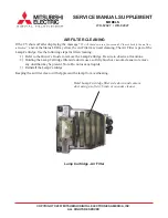
Страница 80: ...MODELS WD 52627 52628 62627 62628 62827 62927 73727 73827 73927 Page 79 Lamp Control Circuitry ...

Страница 81: ...MODELS WD 52627 52628 62627 62628 62827 62927 73727 73827 73927 Page 80 Lamp Engine Fan Protect Circuitry TV Guide On Screen Block Diagram ...

Страница 82: ...GND GND PIC RTS FMT PGOOD TX2_SHIELD AGND YOUT 4 GND PWR ON MAIN Y GND MAIN Pb GND GND GND HDDFANSTP PIC Txd PIC CTS STU R VOUT GND MAIN Pb GND TX1_SHIELD AGND GND GND FAN VCC PBS LCD PON SHORT KSC1 GND CMP2 Y GND GND A GND GND GND TX0_SHIELD AGND LAMP RELAY CRIN 1 STU L RMC GOS CTS FILTER DET IN3 V GND IN2 C ASIC DTOM MAIN H USBNA TXC_SHIELD AGND GND GND GND GLINK Txd STU L GND S3 YOUT 6 GND GND ...

Страница 83: ...9A52 22K 1 16W R9A45 25V C9E45 680U L9A63 2 7MH 2 2 1 10W R9E43 25V C9A70 100U 0 1 C9E50 50V 100 1 10W R9A24 L9A35 6 8MH 9X9 5 35V C9A40 2200U 1 16W R9E64 2 2 0 1 C9E66 50V 16V C9A71 470U 16V C9A99 470U 1K 3W R9A78 1 2W R9A16 180K 1 4W R9A30 68 0 1 C9E12 50V 4700 C9E53 50V 1K 1 16W R9A32 220 1 4W R9A56 HOTGND 47K 1 16W R9A26 L9A31 2 7MH 2SC3052 T112 1E F Q9E50 15K 1 16W R9A10 1 16W R9A59 2 2 220 1...

Страница 84: ... 3 4 5 6 7 8 9 10 11 12 13 14 15 16 17 18 19 20 3 3VSL STATUS G STATUS R LAMP G LAMP R PWR LED MAN RST KSC1 KSC0 STATUS G STATUS R LAMP G LAMP R MAN RST KSC1 KSC0 BALLAST FAN CONT PBS LAMP FAN CONT LCD DLP FAN CONT PWR LED ENG SDA ENG SCL CLRN BUSYX DDAN ENG SCL CLRN BUSYX DDAN ENG SDA LAMPLITZ LAMPEN LAMPLITZ FSTP LAMP FILTER DET COVER DET MD TEMP MD TEMP FAN DET FAN DET ENG PROTECT ENG PROTECT M...

Страница 85: ...3J11 2 7K 1 16W R3J12 0 1 16W R2J46 0 1 16W R2J47 0 1 16W R2J48 0 1 16W R2J45 0 1 16W R2J50 0 1 16W R2J49 0 1 16W R2J51 0 1 16W R2J52 0 1 16W R2J53 0 1 16W R2J54 R2J13 120K 1 16W R2J12 120K 1 16W R2J20 120K 1 16W R2J19 120K 1 16W R2J25 120K 1 16W R2J24 120K 1 16W R2J14 120K 1 16W R2J10 120K 1 16W 120K 1 16W R2J11 120K 1 16W R2J15 D2J01 RSB6 8S D2J02 RSB6 8S D2J04 D2J05 RSB6 8S D2J07 RSB6 8S D2J06 ...

Страница 86: ...MC2838 T112 1 D9F03 MA732 D9F04 MA732 D9F00 1 2 3 4 5 6 7 8 9 10 11 12 1 2 3 4 5 6 7 8 9 10 11 12 13 14 REMOCON PRE AMP UNIT AN PJ2J11 S7L21 KSHS611BT S7L29 KSHS611BT S7L25 KSHS611BT IC7K21 OPA2350PA S7L26 KSHS611BT S7L27 KSHS611BT EP IC80E1 AT24C256N 10SC SI 2 7 IC80E3 24LC64I SN S7L24 KSHS611BT S7L20 KSHS611BT S7L22 KSHS611BT S7L28 KSHS611BT S7L23 KSHS611BT IC80E2 24LC512T I SM LE CE1 CF CD Q9F0...

Отзывы: