


MODELS: WD-52627 / 52628 / 62627 / 62628 / 62827 / 62927 / 73727 / 73827 / 73927
Page 33
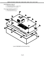
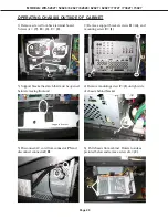
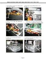
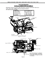
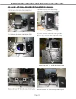
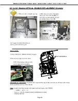
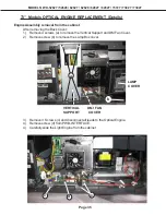
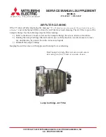
52” & 62” Models OPTICAL ENGINE REPLACEMENT (Details)
Reassembly:
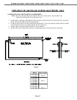
1) Attach LENS CUSHION BASE to Engine
Follow above steps in reverse order
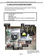
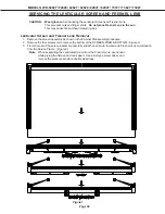
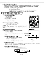
Mechanical Alignment:
Adjustment is required after engine has been removed. Please follow steps
in the adjustment section of this manual.
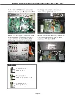
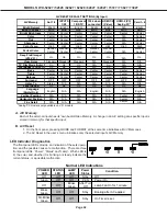
Data:
Index Delay Data needs to be transfered from Engine to E2P PWB:
< MENU + 2457 + 0 >
Select -> COPY LIGHT ENGINE EEPROM TO DM
PRESS ENTER
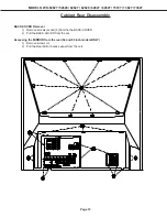
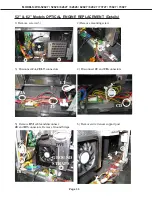
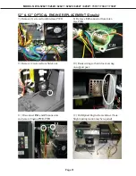
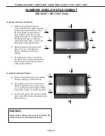
19) Transfer LENS COVER from
service part to defective part
17) Be sure not to misplace spring
18) Remove (1) screw from plate
(A)
, (4) screws from fan
(B)
, (2)
screws from side lock
(C)
and (2)
grounding strap screws
(D)
Lens Cushion Base
Spring
A
B
C
D
TIP: Lift and group wiring on left
side of engine when installing
Содержание WD-52527
Страница 2: ......
Страница 71: ...MODELS WD 52627 52628 62627 62628 62827 62927 73727 73827 73927 Page 70 ...
Страница 72: ...MODELS WD 52627 52628 62627 62628 62827 62927 73727 73827 73927 Page 71 Main Power Supply ...
Страница 75: ...MODELS WD 52627 52628 62627 62628 62827 62927 73727 73827 73927 Page 74 Analog Video Signal Path ...
Страница 76: ...MODELS WD 52627 52628 62627 62628 62827 62927 73727 73827 73927 Page 75 Digital Video Signal Path ...
Страница 78: ...MODELS WD 52627 52628 62627 62628 62827 62927 73727 73827 73927 Page 77 Sound Signal Path ...
Страница 80: ...MODELS WD 52627 52628 62627 62628 62827 62927 73727 73827 73927 Page 79 Lamp Control Circuitry ...