※
Specification may be subject to change without notice.
DATE
TYPE
Heat Recovery Ventilator LOSSNAY
MODEL
VL-350CZPVU-R-E
4/6
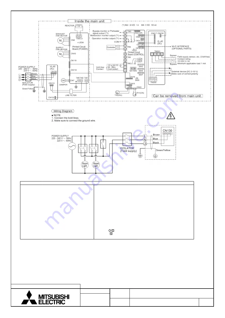
WIRING DIAGRAMS
12-Jan-21
NUMBER
N19SGGD0003B
■
Wiring diagrams
M1
Motor for exhaust fan
CN18, CN19, CN118, CN119
Connector
M2
Motor for supply fan
CN130, CN131,CN132, CN232
Connector
GM
Motor for By-pass damper
CN217, CN26, CN32
Connector
TH1
Thermistor for outside air
CN22
Connector (Thermistor OA)
TH2
Thermistor for return air
CN5
Connector (Thermistor RA)
TM2
Terminal block (External cotrol input)
CN7
Connector (Motor for By-pass damper)
TM4
Terminal block (Remote controler)
TM3
Terminal block (Monitor output)
LED1 to LED4
Inspection indicator lamp
TM200
Terminal block (DC 0-10V)
LED6
Power supply indicator lamp
TM201
Terminal block (Volt-free)
SA1
Address setting rotary switch (10 digit)
TAB1, TAB2
Connector (Power supply)
SA2
Address setting rotary switch (1 digit)
TAB3,4
Connector (Reactor)
SW2, SW5 to SW7
Switch
TAB5
not in use
CN9, CN10
Connector (Fan motor)
SYMBOL
Terminal block
CN17 to CN20
Connector
Connectoron PCB
CN105
Connector (IT)
Definition of symbols
■
Attention
1.
Electrical work must be carried out safely and reliably by a professional electrical contractor (properly qualified
electrician) in accordance with internal wiring provisions and electrical-equipment technical standards.
2.
Use 220 to 240V AC Power.
3.
Use the designated electric wires, and connect them securely so that they do not come loose.
4.
Be sure to install the ground wire.
5.
Install an all-pole power supply isolator at the power supply side as per local electrical regulations. All supply
circuits must be disconnected before obtaining access to the terminal devices. Use the specified cable size and
connect the cables securely to prevent disconnection when they are pulled.
Содержание VL-350CZPVU-R-E
Страница 8: ......


