background image

27

9-5. EMERGENCY OPERATION  

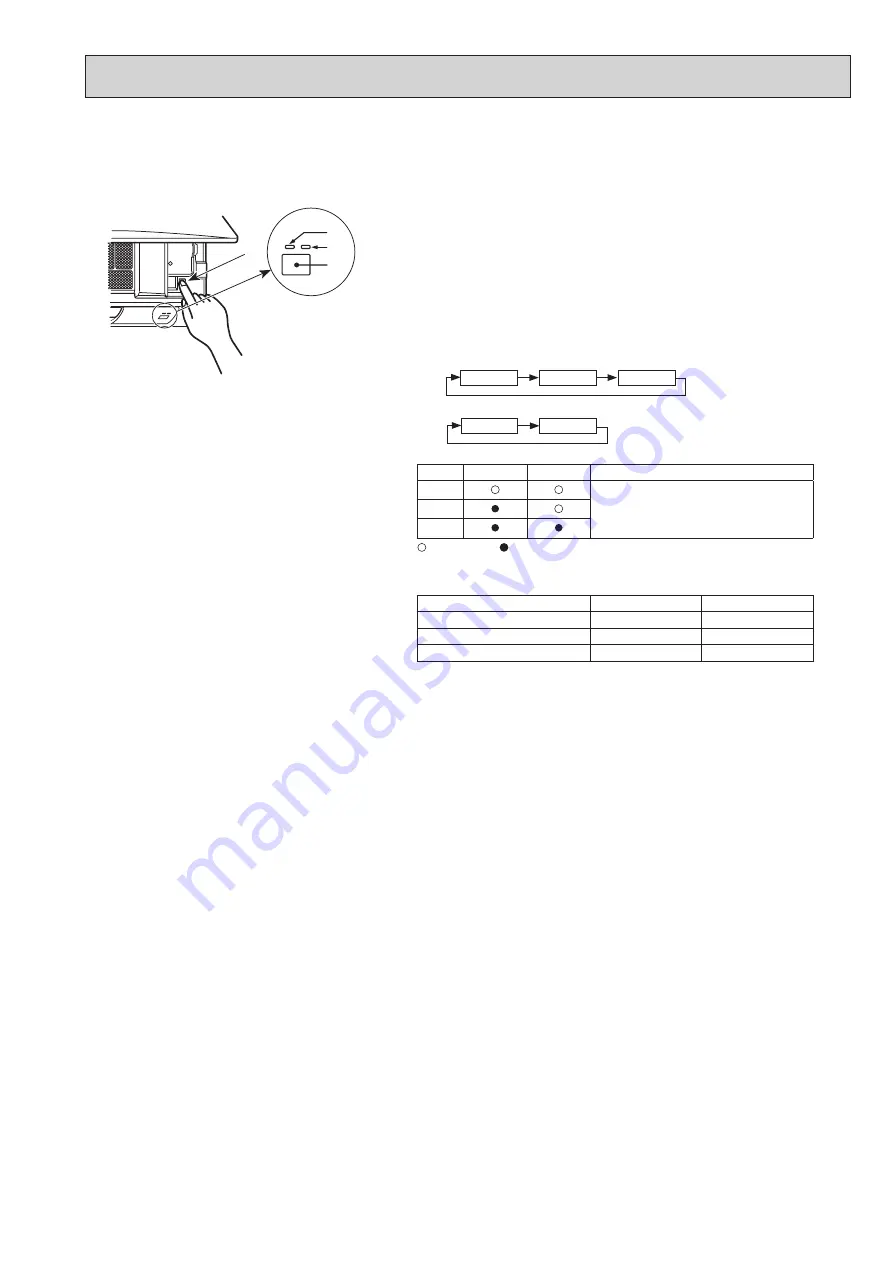
9-5-1. When wireless remote controller troubles or its battery is exhausted


9-5-2. When wired remote controller or indoor unit microprocessor troubles


When the remote controller cannot be used

A

 DEFROST/STAND BY lamp (ORANGE)

B

 Operation lamp (GREEN)

C

 Emergency operation switch (cooling/heating)


D

 Receiver

[Heat pump type]

[Cooling Only type]

Operation Monitor Display

GREEN

ORANGE

STOP

COOL

HEAT

 Turning off 

 Lighting

Details of emergency mode are as shown below.

Operation Mod

Set Temperature

Fan Speed

COOL

HEAT

24°C

24°C

High

High

Airflow Direction Up and Down

Horizontal

Cooling

Heating

Stop

Cooling

Stop

  Each press of the emergency operation switch will toggle the operation mode.

  Check “COOL/HEAT” with the operation monitor display. (The display will

appear orange for 5 seconds after pressing the emergency operation switch.)

Downward

When the batteries of the remote controller run out or the remote controller 

malfunctions, the emergency operation  can be done using the emergency 

buttons.

The orange lamp follows the switch operation 

as indicated at the left for 5 seconds, and 

then it will return to the normal display.

B
A
D

C

1. When the wired remote control or the indoor unit microprocessor has failed, but all other components work properly,
    if you set the switch (SWE) on the indoor controller board ON, the indoor unit will begin Emergency Operation.
    When Emergency Operation is activated, the indoor unit operates as follows:

(1) Indoor fan is running at high speed.  (2) Drain pump is operating.

Note on the wireless remote control:

   When the remote control does not function, it is possible to activate Emergency Operation by using the indoor unit Emergency Operation switch.
   However, if the indoor unit microcomputer has failed, it is necessary to proceed with points 2 and 3 below as in the 
   case of the wired remote control.

2. When you activate Emergency Operation of the cooling or heating, you have to set the switch (SWE) on the indoor
    controller board and activate Emergency Operation of the outdoor unit.
    For details on how to activate Emergency Operation of the outdoor unit, refer to the outdoor unit wiring diagram.

3. Before you activate Emergency Operation, check the following points:

(1) Emergency Operation cannot be activated when:

     • the outdoor unit malfunctions.  • the indoor fan malfunctions.

     • it has detected the malfunction of drain pump during self-diagnosing.

(2) Emergency Operation becomes continuous only by switching the power source on/off.
     ON/OFF on the remote control or temperature control, etc. does not function.
(3) Avoid operating for a long time when the outdoor unit begins defrosting while Emergency Operation of the heating 
     is activated, because it will start to blow cold air.
(4) Emergency cooling should be limited to 10 hours maximum (The indoor unit heat exchanger may freeze).
(5) After Emergency Operation has been deactivated, set the switches, etc. to their original positions.
(6) Movement of the vanes does not work in Emergency Operation, therefore you have to slowly set them manually 
     to the appropriate position.

OCH661

Содержание PKA-M100KA.TH

Страница 1: ...ES AND DIMENSIONS 12 7 WIRING DIAGRAM 13 8 REFRIGERANT SYSTEM DIAGRAM 15 9 TROUBLESHOOTING 16 10 FUNCTION SETTING 32 11 SPECIAL FUNCTION 33 12 DISASSEMBLY PROCEDURE 36 Indoor unit Model Name Service Ref PARTS CATALOG OCB661 INDOOR UNIT PKA M60KA TH PKA M71KA TH PKA M100KA TH PKA M60KAL TH PKA M71KAL TH PKA M100KAL TH PKA M60KA PKA M71KA PKA M100KA PKA M60KAL PKA M71KAL PKA M100KAL SPLIT TYPE HEAT ...

Страница 2: ... ZRP100 125 140VKA3 PUHZ ZRP100 125 140YKA3 PUHZ ZRP200 250YKA2 PUHZ ZRP100 125 140VKA3 UK PUHZ ZRP100 125 140YKA3R1 UK PUHZ ZRP200 250YKA2 UK OCH645 OCB645 PUHZ P100VHA5 PUHZ P125 140VHA4 PUHZ P100YHA3 PUHZ P125 140YHA2 PUHZ P100VHA5 UK PUHZ P125 140VHA4 UK PUHZ P100YHA3 UK PUHZ P125 140YHA2 UK OCH646 OCB646 PUHZ P200 250YKA2 PUHZ P200 250YKA2 UK OCH647 OCB647 PUHZ SHW112VHA PUHZ SHW112YHA PUHZ S...

Страница 3: ... gauge Gauge manifold Torque wrench Gas leak detector Charge hose Tools for R32 R410A Contamination inside refrigerant piping can cause deterio ration of refrigerant oil etc If dirt dust or moisture enters into refrigerant cycle that can cause deterioration of refrigerant oil or malfunction of com pressor If large amount of mineral oil enters that can cause deterio ration of refrigerant oil etc Ve...

Страница 4: ...12 When performing brazing work be sure to ventilate the room sufficiently Make sure that there are no hazardous or flammable materials nearby When performing the work in a closed room small room or similar location make sure that there are no refriger ant leaks before performing the work If refrigerant leaks and accumulates it may ignite or poisonous gases may be released 13 Do not install the un...

Страница 5: ...igeration Equipment Where electrical components are being changed they shall be fit for the purpose and to the correct specification At all times the manufacturer s maintenance and service guidelines shall be followed If in doubt consult the manufacturer s technical department for assistance The following checks shall be applied to installations using flammable refrigerants The charge size is in a...

Страница 6: ...used However for flammable refrigerants it is important that best practice is followed since flammability is a considera tion The following procedure shall be adhered to remove refrigerant purge the circuit with inert gas evacuate purge again with inert gas open the circuit by cutting or brazing The refrigerant charge shall be recovered into the correct recovery cylinders For appliances containing...

Страница 7: ...nders ensure that only appropriate refrig erant recovery cylinders are employed Ensure that the correct number of cylinders for holding the total system charge are available All cylinders to be used are designated for the recovered refrigerant and labelled for that refrigerant i e special cylinders for the recovery of refrigerant Cylinders shall be complete with pressure relief valve and associate...

Страница 8: ...name Specifications 1 Gauge manifold Use the existing fitting specifications UNF1 2 Use high tension side pressure of 5 3MPa G or over 2 Charge hose Use pressure performance of 5 09MPa G or over 3 Electronic weighing scale 4 Gas leak detector Use the detector for R134a R407 R410A or R32 5 Adaptor for reverse flow check Attach on vacuum pump 6 Refrigerant charge base 7 Refrigerant cylinder R32 or R...

Страница 9: ... Displays whether timer is on or off Buttons used to set the hour and minute of the current time and timer settings h and min buttons display display FAN SPEED display indicates which fan speed has been selected display The vertical direction of air flow is indicated display Blinks when model is selected display display CHECK and TEST RUN display indicate that the unit is being checked or test run...

Страница 10: ...11 5 8 365 14 3 8 21 46 kW A kW K min CFM Pa mmAq kW dB mm inch mm inch mm inch mm inch kg lb Mode Power supply phase cycle voltage Input Running current External finish Panel Heat exchanger Fan Fan drive o No Fan motor output Airflow Low Middle High External static pressure Booster heater Operation control Thermostat Noise level Low Middle High Field drain pipe I D Dimensions Weight W D H INDOOR ...

Страница 11: ... 0 30 0 35 0 40 0 45 0 50 0 55 0 60 0 65 0 70 0 63 125 250 500 1k 2k 4k 8k NC 60 NC 50 Octave band pressure level dB 0dB 20μPa Approximate minimum audible limit on continuous noise NC 40 Octave band center frequencies Hz NC 20 NC 30 High Low 10 0 15 0 20 0 25 0 30 0 35 0 40 0 45 0 50 0 55 0 60 0 65 0 70 0 63 125 250 500 1k 2k 4k 8k NC 60 NC 50 Octave band pressure level dB 0dB 20μPa NC 40 Octave b...

Страница 12: ...tion Emergency operation switch cooling heating Operation lamp DEFROST STAND BY lamp Receiver Knockout hole for right piping Mount board Right side 444 Gas pipe 482 Liquid pipe 585 Drain hose Filter hook Under side Vane auto Knockout hole for lower piping Louver manual Piping connection department Indoor unit outline Wall hole for right rear piping Knockout hole for left rear piping 75 480 Wall ho...

Страница 13: ... WH CN41 WH CN2L RD Refer to tables 1 and 2 LED3 LED1 LED2 SWE ON OFF X1 CN90 WH CN32 WH CN3C BU LDSWE A BU CNP BU CN301 GN LED2 LED1 REC1 RU LDSWE B SWE2 SW tº tº tº CN44 WH CN151 WH CN20 RD CN4F WH 1 1 1 5 2 4 1 4 FUSE CN01 BK CNMF WH 1 6 TH1 TH2 TH5 DP 5 3 1 BK W B OG OG BN OG YE YE YE S3 S2 S1 DB1 5 4 1 1 2 1 1 9 1 3 TB4 TO OUTDOOR UNIT 2 When attaching drain pump option 1 4 FS FLOAT SW CN4F W...

Страница 14: ...2 3 4 5 SETTING CAPACITY 71 ON OFF 1 2 3 4 5 SETTING CAPACITY 100 Table 1 SW1 MODEL SELECTION Table 2 SW2 CAPACITY CODE CN01 BK I B YE OG RD BU GNYE TB2 L N YE OG OG BN TB4 S1 S2 S3 1 3 5 TO OUTDOOR UNIT POWER SUPPLY 1PHASE 230V 50Hz CN105 RD 5 1 The black square indicates a switch position 1 3 CN3C BU SYMBOL SYMBOL NAME NAME I B INDOOR CONTROLLER BOARD FUSE T3 15AL250V CONNECTOR LOSSNAY CONNECTOR...

Страница 15: ...stor TH1 Room temperature Refrigerant flow in cooling Refrigerant flow in heating Strainer 50 Strainer 50 Heat exchanger Refrigerant GAS pipe connection Flare Refrigerant LIQUID pipe connection Flare REFRIGERANT SYSTEM DIAGRAM 8 PKA M60KA TH PKA M70KA TH PKA M100KA TH PKA M60KAL TH PKA M70KAL TH PKA M100KAL TH OCH661 ...

Страница 16: ...ccording to 9 4 TROUBLESHOOTING BY INFERIOR PHENOMENA The trouble is not reoccurring Logged Not logged 1Consider the temporary defects such as the work of protection devices in the refrigerant circuit including compressor poor connection of wiring noise etc Re check the symptom and check the installation environment refrigerant amount weather when the trouble occurred matters related to wiring etc...

Страница 17: ... mode is cancelled Procedure 1 Press the CHECK button twice 2 Press the TEMP buttons 3 Point the remote controller at the sensor on the indoor unit and press the HOUR button 4 Point the remote controller at the sensor on the indoor unit and press the ON OFF button Malfunction diagnosis method at maintenance service 9 2 MALFUNCTION DIAGNOSIS METHOD BY REMOTE CONTROLLER In case of trouble during ope...

Страница 18: ...ote controller Wired remote controller 1 P1 Intake sensor error P9 Pipe TH5 sensor error 2 P2 Pipe TH2 sensor error 3 E6 E7 Indoor outdoor unit communication error 4 P4 Drain sensor error Float switch connector CN4F open 5 P5 PA Drain pump error Forced compressor stop due to water leakage abnormality 6 P6 Freezing Overheating protection operation 7 EE Combination error between indoor and outdoor u...

Страница 19: ... possible due to system startup Correct operation Connector for the outdoor unit s protection device is not connected Reverse or open phase wiring for the outdoor unit s power terminal block L1 L2 L3 Incorrect wiring between indoor and outdoor units incorrect polarity of S1 S2 S3 Remote controller wire short Note Operation is not possible for about 30 seconds after cancellation of function selecti...

Страница 20: ...Check resistance value of thermistor For characteristics refer to P1 above 2 Check contact failure of connector CN44 on the indoor controller board Refer to 9 7 TEST POINT DIAGRAM Turn the power on and check restart after inserting connector again 4 Check pipe liquid temperature with remote controller in test run mode If pipe liquid temperature is extremely low in cooling mode or high in heating m...

Страница 21: ...door fan motor Fan motor is defective Indoor controller board is defec tive 5 Defective outdoor fan control 6 Overcharge of refrigerant 7 Defective refrigerant circuit clogs 8 Bypass circuit of outdoor unit is defective Cooling or drying mode 1 Check clogs of the filter 2 Remove shields 4 Refer to 9 6 How to check the parts 5 Check outdoor fan motor 67 Check operating condition of refrigerant circ...

Страница 22: ...2 Set one of the remote controllers main if there is no problem with the action above 3 Check wiring of remote controller Total wiring length max 500m Do not use cable 3 or more The number of connecting indoor units max 16 units The number of connecting remote controller max 2 units When it is not the above mentioned problem of 1 3 4 Diagnose remote controllers a When RC OK is displayed Remote con...

Страница 23: ...oller circuit board to transmit signals Indoor controller board Abnormal if data cannot be read normally from the nonvolatile memory of the indoor controller board 1 Defective indoor controller board 1 Replace indoor controller board Remote controller control board 1 Abnormal if data cannot be read nor mally from the nonvolatile memory of the remote controller control board Check code E1 2 Abnorma...

Страница 24: ... circuit of float switch 4 Contact failure of float switch connector 5 Dew condensation on float switch Drain water descends along lead wire Drain water is waving due to filter clogging 6 Extension piping connection difference at twin triple or quadruple system 7 Miswiring of indoor outdoor connecting at twin triple or quadruple system 8 Room temperature thermistor liquid pipe temperature thermist...

Страница 25: ...inal block S1 and S2 When 220 240 V AC is not detected check indoor outdoor unit connecting wire for miswiring When 220 240 V AC is detected check 4 below 4 Check the fuse on indoor controller board Check the wiring connection If no problem is found indoor controller board is defective 1 Check the voltage of indoor power supply terminal block L N When 220 240 V AC is not detected check the power s...

Страница 26: ...ck the connection of remote controller wires in the case of twin triple indoor unit system When 2 or more indoor units are wired in one refrigerant system connect remote controller wires to one of those units 2 Check the setting of refrigerant address in case of grouping control system If there are some units whose refrigerant addresses are 0 in one group set one of the units to 0 using SW1 3 6 on...

Страница 27: ...r unit operates as follows 1 Indoor fan is running at high speed 2 Drain pump is operating Note on the wireless remote control When the remote control does not function it is possible to activate Emergency Operation by using the indoor unit Emergency Operation switch However if the indoor unit microcomputer has failed it is necessary to proceed with points 2 and 3 below as in the case of the wired...

Страница 28: ...Brown Yellow 1 5 Brown Green Open or short Fan motor MF 2 Red 4 Yellow 1 Brown Orange 3 Green 5 Connect pin No M Refer to 9 6 2 DC Fan motor fan motor indoor controller circuit board 0 10 20 30 40 50 20 10 0 10 20 30 40 50 Thermistor for lower temperature Temperature Resistance k Thermistor Characteristic Graph Room temperature thermistor TH1 Pipe temperature thermistor liquid TH2 Condenser evapor...

Страница 29: ...VDC 310 340 V DC TEST POINT 2 VCC between 4 and 3 of the fan connector VCC 15 V DC Wiring recovery Replace the indoor controller board Replace the fan motor Replace the indoor controller board Replace the fan motor Is the voltage normal Is there contact failure No 1 2 Yes No Check the operation of fan END Yes OK Check the operation END OK Check method of DC fan motor fan motor indoor controller ci...

Страница 30: ...n SW2 Capacity setting CN151 Connect to the vane motor MV Jumper wire J41 J42 Pair No setting for wireless remote controller CN01 Connect to the Terminal block TB4 1 3 220 240 V AC LED1 Power supply I B LED2 Power supply R B LED3 Transmission Indoor outdoor CN3C Transmission Indoor outdoor 0 24 V DC CN4F Float switch FS option CN22 Connect to the terminal block TB5 Remote controller connecting wir...

Страница 31: ...pported The pair number settings of the wireless remote controller and indoor control PCB J41 J42 are given in the table on the left For product Service parts Indoor controller board type JP3 With JP3 Without JP3 Marks in the table below Jumper wire Short Open The black square indicates a switch position MODELS SETTING PKA M KA L MODELS SETTING PKA M60KA L PKA M71KA L PKA M100KA L ON OFF 1 2 3 4 5...

Страница 32: ... the unit number to 00 Refer to the service manual that comes with each outdoor unit 2 Functions available when setting the unit number to 01 03 or AL 07 in case of wireless remote controller Function Settings Mode No Setting No Initial setting Setting Filter sign 100 Hr 07 1 2500 Hr 2 No filter sign indicator 3 Fan speed Silent 08 1 Standard 2 High ceiling 3 Fan speed during the cooling thermosta...

Страница 33: ...k up function Outline of functions Main and sub unit operate alternately according to the interval of rotation setting Main and sub unit should be set by refrigerant address Outdoor DIP switch setting Refrigerant address 00 Main unit Refrigerant address 01 Sub unit When an error occurs to one unit another unit will start operation Back up function System constraint This function is available only ...

Страница 34: ...oring the request code of current setting Setting contents Rotation ON Alternating interval 28days and back up function Rotation ON Alternating interval 14days and back up function Rotation ON Alternating interval 1day and back up function Back up function only No 5 324 Rotation ON Alternating interval 7days and back up function Rotation ON Alternating interval 5days and back up function Rotation ...

Страница 35: ... and press the button Set the Refrigerant address and Request code Select the item to be changed with the F1 or F2 button Select the required setting with the F3 or F4 button Select the required code No 311 318 321 324 with the F3 or F4 button Ref address setting 0 15 Request code setting Press the button Data will be collected and displayed Request code 311 Rotation and Back up OFF 0311 Select Se...

Страница 36: ...s each 1 screw See Photo 2 3 Disconnect the connectors on the indoor controller board See Photo 3 4 Remove the switch board holder and open the cover 5 Pull out the indoor controller board toward you then remove the indoor controller board and switch board See Photo 3 6 Remove the holder of wireless remote controller board 7 Disconnect the connector of wireless remote controller board and remove t...

Страница 37: ...r box Refer to procedure 1 2 Remove the electrical box covers Refer to procedure 2 3 Disconnect the vane motor connector CN151 on the indoor controller board 4 Pull out the drain hose from the nozzle assembly and remove nozzle assembly See Photo 5 Photo 4 Photo 5 Photo 6 5 Removing the vane motor 1 Remove the nozzle assembly Refer to procedure 4 2 Remove 2 screws of the vane motor unit cover and p...

Страница 38: ...f the heat exchanger See Photo 9 10 Lift the heat exchanger and pull out the line flow fan to the lower left Photo 7 7 Removing the pipe temperature thermistor liquid TH2 and cond eva temperature thermistor TH5 1 Remove the panel and the corner box Refer to procedure 1 2 Remove the electrical box covers Refer to procedure 2 3 Remove the water cut See Photo 2 4 Remove the pipe temperature thermisto...

Страница 39: ... left side of the heat exchanger See Photo 9 7 Remove the heat exchanger 9 Removing the room temperature thermistor 1 Remove the panel and corner box Refer to procedure 1 2 Remove the electrical box covers 3 Remove the room temperature thermistor 4 Disconnect the connector CN20 on the indoor controller board Photo 11 Photo 12 Photo 13 Heat exchanger Water cut Indoor controller board I B Room temp ...

Страница 40: ...ICE TOKYO BUILDING 2 7 3 MARUNOUCHI CHIYODA KU TOKYO 100 8310 JAPAN CCopyright 2017 MITSUBISHI ELECTRIC CORPORATION Published Mar 2017 No OCH661 Made in Japan Specifications are subject to change without notice ...

Страница 41: ... Power Inverter Brochure R32 PKA M R32 Power Inverter Product Information Sheet PKA M60 100KA Declaration of Conformity PKA M60 100KA Installation Manual PKA M60 100KA Operation Manual PKA M60 100KA Parts List PKA M60 100KA Service Manual OCH661 ...

Отзывы: