background image

– 10 –

9. Turning on the power

Make sure that the MA remote controller is properly installed according to the instructions in the Installation Manual and that the indoor and 
outdoor unit installation has been completed before turning on the power.

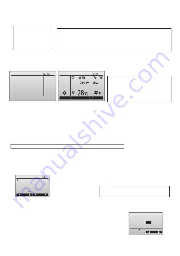
(1) When the power is turned on, the following screen will appear.

(2) Main display

After the successful startup, the Main display will appear. The Main display can be displayed in two different modes: "Full" and "Basic." 
Refer to section 11 "Initial settings" for how to select the display mode. (The factory setting is "Full.")

10. Test run <Maintenance password is required.>

(1) Read the section about Test run in the indoor unit Installation Manual before performing a test run.

(2) At the Main display, press the MENU button and select Service>Test run>Test run.

(3) Press the ON/OFF button to cancel the test run if necessary.

(4) Refer to the indoor unit Installation Manual for the detailed information about test run and for how to handle the errors that occur during 

a test run.

11. Initial settings (Remote controller settings)

<Administrator password is required.>

From the Main display, select Main menu>Initial setting, and make the remote controller settings on the screen that appears.

(1) Main/Sub setting

When connecting two remote controllers, one of them needs to be designated as a sub controller.

Notes

· When the power is on for the first time, the Language selection screen will be displayed. Refer 

to section 11 (8). Select a desired language. The system will not start-up without language 
selection.

· Some models of City Multi cannot have more than one remote controller connected. Refer to 

relevant documents (e.g., catalogs) for usage compatibility.

Normal start up (indicating the 

percentage of process completion)

Notes

· When connecting two remote controllers, be sure 

to designate one as a main and the other as a sub 
controller. Refer to section 11 "Initial settings" for 
how to make the Main/Sub setting.

· Refer to the Instructions Book for the icons on the 

display.

Main display in the Full mode

 (while the unit is not in operation)

Main display in the Full mode

 (while the unit is in operation)

Note: Refer to section 12 "Service menu" for information about the maintenance password.

Initial setting menu (1/2)
· Main/Sub
· Clock
· Main display
· Contrast
· Display details
  -Clock
  -Temperature
  -Room temp.
  -Auto mode

Initial setting menu (2/2)
· Auto mode
· Administrator password
· Language selection

Note: The initial administrator password is "0000." Refer 

to section (7) "Administrator password setting" for 
how to change the password.

[Button operation]

[1] When the F3 or F4 button is pressed, the currently selected setting will appear highlighted. 

Select "Sub", and press the SELECT button to save the change.

[2] Press the MENU button to return to the Main menu screen. (This button always brings up the 

Main menu screen.)

Please Wait

10%

Fri

Fri

Cool

Room

Auto

Set temp.

Mode

Temp.

Fan

Initial setting menu

Main menu:

Cursor

Page

Main/Sub
Clock
Main display
Contrast
Display details

Main/Sub

Main /

Sub

Select:

Cursor

WT06695X01_2_GB_A5.fm  Page 2  Tuesday, August 7, 2012  3:39 PM

Содержание PAR-31MAA

Страница 1: ...nel Do not install the unit in a place where large amounts of oil steam organic solvents or corrosive gases such as sulfuric gas are present or where acidic alkaline solutions or sprays are used frequently These substances can compromise the performance of the unit or cause certain components of the unit to corrode which can result in electric shock malfunctions smoke or fire To reduce the risk of...

Страница 2: ...risk of electric shock shorting or malfunctions keep wire pieces and sheath shavings out of the terminal block To reduce the risk of shorting current leakage electric shock or malfunctions keep the cables out of contact with controller edges To reduce the risk of electric shock malfunctions or fire seal the gap between the cables and cable access holes with putty The controller should be repaired ...

Страница 3: ...he box WARNING The CD ROM that is supplied with the Remote Controller can only be played on a CD drive or a DVD drive Do not attempt to play this CD ROM on an audio CD player as this may damage your ears and or speakers 4 The front cover 1 is already installed on the top case 2 at factory shipment 5 Remote controller cable is not included To avoid damage to the controller provide protection agains...

Страница 4: ... the remote controller where no wires are routed around the temperature sensor on the controller If wires are routed the sensor cannot measure accurate indoor temperature Parts name Qty Notes Double switch box 1 Not required for direct wall installation Thin metal conduit Necessary Lock nut and bushing Necessary Cable cover Necessary Required for routing remote controller cable along a wall Putty ...

Страница 5: ...troller cable access hole at the connection of switch box and conduit tube with putty 3 Prepare the bottom case of the remote controller Direct wall installation Seal the hole through which the cable is threaded with putty To reduce the risk of electric shock malfunctions or fire seal the gap between the cables and cable access holes with putty Wall Conduit tube Locknut Switch box Seal the gap wit...

Страница 6: ...n the cover indicated with the shaded area in the right figure with a knife or a nipper Thread the cable from the groove behind the bottom case through this access hole Installation using a switch box Direct wall installation Seal the cable access hole with putty Double switch box Roundhead cross slot screws Remote controller cable Wood screw Remote controller cable Thread the cable through the gr...

Страница 7: ...bottom of the remote controller and move it in the direction of the arrow as shown in the figure at right Hold the cables in place with clamps to prevent undue force from being applied to the terminal block and causing cable breakage Important Clamp Insert the wire When attaching the cover and the top casing to the bottom casing push it until it they click into place If they are not properly locke...

Страница 8: ...the protective sheet on the operation interface prior to use 3 Installing the cover and top case Two mounting tabs are at the top of the top case Hook those two tabs onto the bottom case and click the top case into place Install the cover on the top case in the same way as with the top case Check that the top case is securely installed and not lifted Note When temperature changes rapidly the tempe...

Страница 9: ... Cursor Page Main menu Vane Louver Vent Lossnay High power Timer Weekly timer OU silent mode Page Cursor Move the cursor to the desired function with the F1 and F2 buttons and press the SELECT button to go to the next page Password may be required The function of the MENU SELECT and RETURN buttons will appear on the setting screens Button function guide will appear at the bottom of the screens Pre...

Страница 10: ...creen will be displayed Refer to section 11 8 Select a desired language The system will not start up without language selection Some models of City Multi cannot have more than one remote controller connected Refer to relevant documents e g catalogs for usage compatibility Normal start up indicating the percentage of process completion Notes When connecting two remote controllers be sure to designa...

Страница 11: ...ange to bring up the clock display setting screen Use the F1 through F4 buttons to select Yes display or No non display and its format for the Main display Save the settings with the SELECT button The factory settings are Yes display and 24 h format Clock display Yes Time is displayed on the Main display No Time is not displayed on the Main display Display format 24 hour format 12 hour format AM P...

Страница 12: ...and set each number 0 through 9 with the F3 or F4 button 2 Press the SELECT button Note The initial administrator password is 0000 Change the default password as necessary to prevent unauthorized access Have the password available for those who need it Note If you forget your administrator password you can initialize the password to the default password 0000 by pressing and holding the F1 and F2 b...

Страница 13: ... following settings can be made from the Maintenance Information screen Registering model names and serial numbers Enter the model names and serial numbers of outdoor and indoor units The information entered will appear on the Error information screen Model names can have up to 18 characters and the serial numbers can have up to 8 characters Registering dealer information Enter phone number of a d...

Страница 14: ... 1 2 3 4 or All for the Unit number These settings apply to each indoor unit If 1 2 3 or 4 is set for the Unit number the settings apply only to the specified indoor unit regardless of the number of connected indoor units one through four units If ALL is set for the Unit number the settings apply to all the connected indoor units regardless of the number of connected indoor units one through four ...

Страница 15: ... 2 Other options in the Check menu Mr Slim only The following options are also available on the Mr Slim units in the Check menu Deleting the error history To delete the error history press the F4 button Delete on the screen that shows error history A confirmation screen will appear asking if you want to delete the error history Press the F4 button OK to delete the history Refrigerant volume check ...

Страница 16: ...Resetting the error history 1 Press the F4 button Reset on the screen that shows the error history A confirmation screen will appear asking if you want to delete the error history 2 Press the F4 button OK to delete the error history If deletion fails Request rejected will appear and Unit not exist will appear if no indoor units that are correspond to the entered address are found Procedures 1 Sele...

Отзывы: