30
MSZ-D30NA MSZ-D36NA MSY-D30NA MSY-D36NA
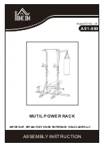
Indoor electronic control P.C. board
9-7. TEST POINT DIAGRAM AND VOLTAGE
Indoor coil thermistor [RT12 (MAIN), RT13 (SUB)]
Room temperature thermistor (RT11)
Temperature (°F)
Resistance (kΩ)
40
30
20
10
0
32 50 68 86 104 122 140
(+)0 V DC or
15 V DC
SM76A017G01
230 V AC
Fuse (F11)
T3.15AL250V
Indoor coil thermistor/
RT12 (CN112)(MAIN)
RT13 (CN112)(SUB)
Horizontal vane
motor (CN151)
SW P.C. board
Power monitor
receiver
P.C. board
12 V DC
5 V DC
(+)3-6 V DC
15 V DC
(-) Fiducial terminal of
cathode side on measur-
ing high-voltage DC
325 V DC
Power supply input
Indoor fan motor
(CN211)
}
Varistor (NR11)
Room temperature
thermistor/RT11
(CN111)
}
Timer short
mode point
JPG, JPS
(Refer to 7-1.)
Vertical vane motor (CN152)
Release of Auto restart function
Solder the Jumper wire to JR07
(Refer to 7-3.)
Cement resistor (R111)
approximately 4Ω
(+)
(-)
Receiver P.C.board connector
(CN301)
OBH501D