background image

19

a

d

c

b

e

f

90°

d

c

b

a

b

a

a

b

e

b

c

d

c

A

Fig. 5-3

5. Refrigerant piping work

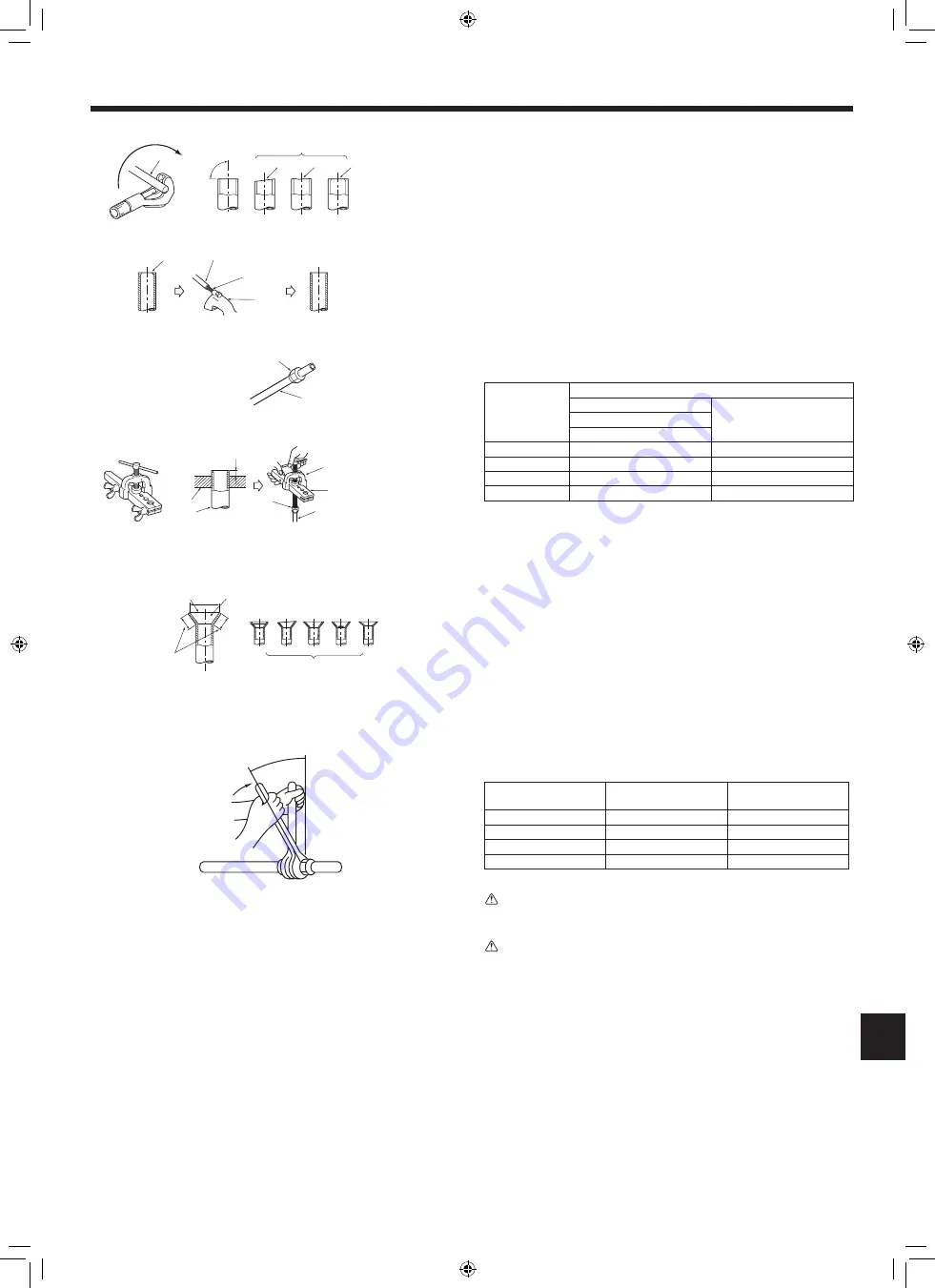
5.2.5. Check (Fig. 5-7)

•  Compare the flared work with a figure in right side hand.

•  If flare is noted to be defective, cut off the flared section and do flaring work again.

a

 Smooth all around

f

 Scratch on flared plane

b

 Inside is shining without any scratches

g

 Cracked

c

 Even length all around

h

 Uneven

d

 Too much

i

 Bad examples

e

 Tilted

•  Apply a thin coat of refrigeration oil on the seat surface of pipe. (Fig. 5-8)

•  For connection first align the center, then tighten the first 3 to 4 turns of flare nut.

•  Use tightening torque table below as a guideline for indoor unit side union joint 

section, and tighten using two wrenches. Excessive tightening damages the flare 

section.

Copper pipe O.D.

(mm)

Flare nut O.D.

(mm)

Tightening torque

(N·m)

ø6.35

17

14 - 18

ø9.52

22

34 - 42

ø12.7

26

49 - 61

ø15.88

29

68 - 82

 Warning:

When installing the unit, securely connect the refrigerant pipes before starting 

the compressor.

 Warning:

Be careful of flying flare nut! (Internally pressurized)

Remove the flare nut as follows:

1. Loosen the nut until you hear a hissing noise.

2. Do not remove the nut until the gas has been completely released (i.e., hiss

-

ing noise stops).

3. Check that the gas has been completely released, and then remove the nut.

Fig. 5-7

Fig. 5-4

Fig. 5-5

Fig. 5-6

a

 Copper tubes

b

 Good

c

 No good

d

 Tilted

e

 Uneven

f

 Burred

a

 Burr

b

 Copper tube/pipe

c

 Spare reamer

d

 Pipe cutter

a

 Flare nut

b

 Copper tube

a

 Flaring tool

b

 Die

c

 Copper tube

d

 Flare nut

e

 Yoke

Fig. 5-8

c

b

a

d

e

f

g

h

i

B

5.2. Flaring work

•  Main cause of gas leakage is defect in flaring work.
  Carry out correct flaring work in the following procedure.

5.2.1. Pipe cutting (Fig. 5-3)

•  Using a pipe cutter cut the copper tube correctly.

5.2.2. Burrs removal (Fig. 5-4)

•  Completely remove all burrs from the cut cross section of pipe/tube.

•  Put the end of the copper tube/pipe to downward direction as you remove burrs in 

order to avoid burrs drop in the tubing.

5.2.3. Putting nut on (Fig. 5-5)

•  Remove flare nuts attached to indoor and outdoor unit, then put them on pipe/tube 

having completed burr removal.

(not possible to put them on after flaring work)

5.2.4. Flaring work (Fig. 5-6)

•  Carry out flaring work using flaring tool as shown at the right.

Pipe diameter

(mm)

Dimension

A (mm)

B

+0

    (mm)

-0.4

When the tool for R32 is used

Clutch type

6.35

0 - 0.5

9.1

9.52

0 - 0.5

13.2

12.7

0 - 0.5

16.6

15.88

0 - 0.5

19.7

Firmly hold copper tube in a die in the dimension shown in the table at above.

VH79A008H01_En.indd   19

2018/10/05   10:12:11

Содержание Mr.Slim SUZ-M-VA-ER Series

Страница 1: ...R Series FOR INSTALLER INSTALLATION MANUAL For safe and correct use read this manual and the indoor unit installation manual thoroughly before installing the air conditioner unit English VH79A008H01_En indd 1 2018 10 05 10 12 08 ...

Страница 2: ...k The use of defective parts could cause an injury or leakage of water due to a fire an electric shock the unit falling etc Ventilate the room if refrigerant leaks during operation If the refrigerant comes in contact with a flame poisonous gases will be released When pumping down the refrigerant stop the compressor before disconnecting the refrigerant pipes The compressor may burst if air etc get ...

Страница 3: ... appropriate ventilation Where it is not exposed to strong wind Where airflow is good and dustless Where it is not exposed to rain and direct sunshine Where neighbours are not annoyed by operation sound or hot air Where rigid wall or support is available to prevent the increase of operation sound or vibration Where there is no risk of combustible gas leakage When installing the unit at a high leve...

Страница 4: ...efrigerant C Create an appropriate ventilation open area Make sure that the width of the open area is 0 9 m or more and the height of the open area is 0 15 m or more However the height from the bottom of the installation space to the bottom edge of the open area should be 0 125 m or less Open area should be 75 or more opening B Install in a space with a depression height of 0 125 m Amin Height fro...

Страница 5: ...ual Install the indoor unit so that the height from the floor to the bottom of the indoor unit is h0 for wall mounted 1 8 m or more for ceiling suspended cassette and ceiling concealed 2 2 m or more There are restrictions in installation height for each model so read the installation manual for the particular unit M kg Amin m 1 0 4 1 5 6 2 0 8 2 5 10 3 0 12 3 5 14 4 0 16 4 5 20 5 0 24 5 5 29 6 0 3...

Страница 6: ...hen operating the air conditioner in low outside temperature be sure to fol low the instructions described below Never install the outdoor unit in a place where its air inlet outlet side may be ex posed directly to wind To prevent exposure to wind install the outdoor unit with its air inlet side facing the wall To prevent exposure to wind it is recommended to install a baffle board on the air outl...

Страница 7: ... table below Refrigerant to be added M25 20 g refrigerant piping length m 7 0 91 M35 20 g refrigerant piping length m 7 1 16 M50 20 g refrigerant piping length m 7 1 66 M60 20 g refrigerant piping length m 7 1 71 M71 40 g refrigerant piping length m 7 2 37 1 Table below shows the specifications of pipes commercially available Model Pipe Outside diameter Min wall thickness Insulation thickness Insu...

Страница 8: ... been completely released i e hiss ing noise stops 3 Check that the gas has been completely released and then remove the nut Fig 5 7 Fig 5 4 Fig 5 5 Fig 5 6 a Copper tubes b Good c No good d Tilted e Uneven f Burred a Burr b Copper tube pipe c Spare reamer d Pipe cutter a Flare nut b Copper tube a Flaring tool b Die c Copper tube d Flare nut e Yoke Fig 5 8 c b a d e f g h i B 5 2 Flaring work Main...

Страница 9: ...the vacuum with the gage manifold valve then close the gage manifold valve and stop the vacuum pump Leave it as is for one or two minutes Make sure the pointer of the gage mani fold valve remains in the same position Confirm that the pressure gage show 0 101 MPa 760 mmHg PURGING PROCEDURES Remove the gage manifold valve quickly from the service port of the stop valve Run the vacuum pump Vacuumize ...

Страница 10: ...ter etc Tighten terminal screws securely Wiring should be done so that the power lines are not subject to tension Otherwise heat may be generated or fire may occur A B C D S3 S3 S2 S1 1 S 2 S L N 2 1 E B C L N A E D C Fig 6 1 Fig 6 2 A Indoor unit B Outdoor unit C Wired main switch Earth leakage breaker D Earth E Remote controller For Power supply Indoor terminal block Earth wire green yellow Indo...

Страница 11: ...iring size must comply with the applicable local and national code 2 Power supply cords and Indoor Outdoor unit connecting cords shall not be lighter than polychloroprene sheathed flexible cord Design 60245 IEC 57 3 Install an earth longer than other cables 4 Use self extinguishing distribution cables for power supply wiring 5 Properly route wiring so as not to contact the sheet metal edge or a sc...

Страница 12: ...r pump down the system following the procedure below so that no refrigerant is released into the atmosphere 1 Turn off the power supply circuit breaker 2 Connect the gauge manifold valve to the service port of the stop valve on the gas pipe side of the outdoor unit 3 Fully close the stop valve on the liquid pipe side of the outdoor unit 4 Supply power circuit breaker 5 Perform the refrigerant coll...

Страница 13: ...n burns or frostbite Never put batteries in your mouth for any reason to avoid accidental ingestion Battery ingestion may cause choking and or poisoning Install the unit on a rigid structure to prevent excessive operation sound or vibration The A weighted sound pressure level is below 70dB This appliance is intended to be used by expert or trained users in shops in light industry and on farms or f...

Страница 14: ...PEC NAME PLATE P Sequential number for each unit 00001 99999 P Product code of outdoor Month of manufacture 1 2 3 4 5 6 7 8 9 X 10 Y 11 Z 12 Year of manufacture western calendar 2015 5 2016 6 VH79A008H01_Cover_plus indd 2 2018 09 27 16 57 30 ...

Страница 15: ...mber on this manual before handing it to the customer HEAD OFFICE TOKYO BUILDING 2 7 3 MARUNOUCHI CHIYODA KU TOKYO 100 8310 JAPAN This product is designed and intended for use in the residential commercial and light industrial environment VH79A008H01_Cover_plus indd 3 2018 09 27 16 57 30 ...

Отзывы: