


Eng-19
English
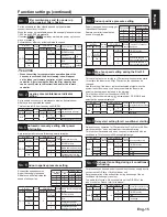
No.54
Automatic ventilation mode setting 3)
The lowest indoor temperature setting
6HWRQHRIFRQGLWLRQVIRU%\SDVVPRGHLQDXWRYHQWLODWLRQRSHUDWLRQ
minimum indoor temperature.
This function is N/A from Lossnay unit DIP-SW.
This function is available when setting Data 3 is selected at function
No. 51
.
:KHQ/RVVQD\LVLQWHUORFNHGWR0U6OLPRU&LW\0XOWLLQGRRUXQLWWKH
target temperature of the indoor unit is the lowest indoor temperature
for By-pass mode
DIP-SW
Setting
check
3='5(
Setting
check
Indoor temperature
SW No.
Setting
Function No. Setting Data
N/A
-
-
54
0
Û&RUPRUH
-
-
1
)DFWRU\VHWWLQJ
Û&RUPRUH
-
-
2
Û&RUPRUH
-
-
3
Û&RUPRUH
-
-
4
Û&RUPRUH
-
-
5
Û&RUPRUH
-
-
6
Û&RUPRUH
-
-
Û&RUPRUH
-
-
Û&RUPRUH
-
-
9
Û&RUPRUH
-
-
10
Û&RUPRUH
-
-
11
Û&RUPRUH
-
-
12
Û&RUPRUH
-
-
13
Û&RUPRUH
-
-
14
Û&RUPRUH
-
-
15
Û&RUPRUH
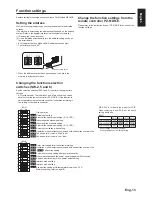
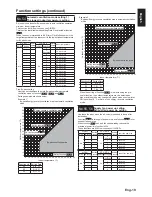
Free By-pass setting
User can set conditions to go into By-pass mode in automatic
ventilation mode by function
No. 52
No. 53
and
No. 54
.
Setting examples are shown below.
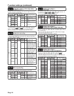
Example 1*
By-pass/Energy recovery ventilation map in automatic ventilation
mode
Function No. Setting Data
52
Û&
53
Û&
54
Û&
8
8
10
12
14
16
18
20
22
24
26
28
30
32
34
36
38
40
12
10
14
18
16
20 22 24 26 28 30 32 34 36 38 40
2XWGRRUWHPSHUDWXUHÛ&
,QGRRUWHPSHUDWXUHÛ&
Set by function
No. 53
Energy recovery ventilation area
By-pass ventilation area
Set by function
No. 52
Set by function
No. 54
(Terget temp. of air
FRQGLWLRQHU
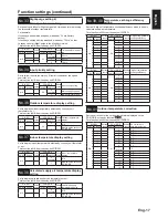
Function settings (continued)
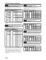
Example 2
By-pass/Energy recovery ventilation map in automatic ventilation
mode
Function No. Setting Data
52
Û&
53
Û&
54
Û&
When the setting of Function
No. 53
LVORZZLWKXVLQJWKHSUH
KHDWHUIXQFWLRQWKHRXWGRRUWHPSHUDWXUHPD\EHGHWHFWHGDV
higher and the mode may change to By-pass mode even in winter.
6HWWKHVHWWLQJÛ&RUPRUHRUXVHHQHUJ\UHFRYHU\YHQWLODWLRQ
mode.
1R
Supply fan power up setting
Exhaust fan power up setting
Use these functions when the air volume is needed to be up after
installation.
Function
No. 55
is for supply fan power up and function
No. 56
is for
exhaust fan power up.
When function
No. 1
is on and fan speed already reached the
PD[LPXPSRZHUWKLVIXQFWLRQLV1$
These functions are N/A from Lossnay unit DIP-SW.
DIP-SW
Setting
check
3='5(
Setting
check
Supply fan power up
SW No.
Setting
Function No. Setting Data
N/A
-
-
55
0
)DFWRU\VHWWLQJ
N/A
-
-
1
1 level up
-
-
2
2 level up
-
-
3
3 level up
-
-
4
4 level up
DIP-SW
Setting
check
3='5(
Setting
check
Exhaust fan power up
SW No.
Setting
Function No. Setting Data
N/A
-
-
56
0
)DFWRU\VHWWLQJ
N/A
-
-
1
1 level up
-
-
2
2 level up
-
-
3
3 level up
-
-
4
4 level up
8
8
10
12
14
16
18
20
22
24
26
28
30
32
34
36
38
40
12
10
14
18
16
20 22 24 26 28 30 32 34 36 38 40
2XWGRRUWHPSHUDWXUHÛ&
,QGRRUWHPSHUDWXUHÛ&
Energy recovery ventilation area
By-pass ventilation area
Set by function
No. 53
Set by function
No. 52
Set by function
No. 54
(Terget temp. of air
FRQGLWLRQHU


