


Eng-12
SW1
CN26
CN26
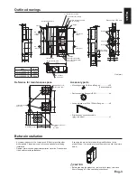
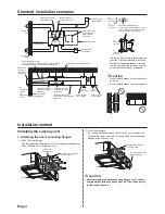
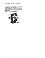
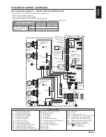
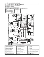
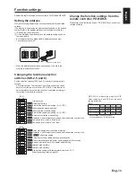
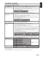
Installation method (continued)
S
B
A
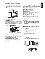
TB5
M-NET transmission cable
Shielded wire
M-NET transmission cable input terminal block
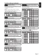
When switching By-pass externally.
To change fan speed by 0 - 10 VDC input
9
Establish the wire connection by inserting the optional remote display
DGDSWRU3$&6$+$(LQWKHFRQQHFWRU&1:KLWH
Establish the wire connection by inserting the optional remote display
DGDSWRU3$&6$+$(LQWKHFRQQHFWRU&1:KLWH
7RFKDQJHIDQVSHHGE\9'&LQSXWWKHZLULQJVKRXOGEHWKH
DERYHSLFWXUH5HIHUWRIXQFWLRQVHWWLQJV
No. 63
for more details.
With SW1 is “ON”
WKHYHQWLODWLRQPRGHRI/RVVQD\LVFKDQJHGWRWKH
By-pass ventilation regardless of the setting on the remote controller.
:KHQWKHRXWGRRUDLUWHPSHUDWXUHGURSVORZHUWKDQÛ&LW
changes to the heat exchanger ventilation. (Display of the
UHPRWHFRQWUROOHUGRHVQRWFKDQJH
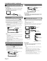
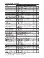
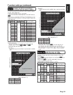
When using the remote/local switching and the ON/OFF
input (level signal)
10
,QVHUWWKHRSWLRQDOUHPRWH212))DGDSWRU3$&6(5$(LQ
CN32 on the Lossnay control PCB.
5HPRWHFRQWURO
board
5HPRWH212))DGDSWRU
2SWLRQDO3$&6(5$(
Lossnay
control board
5HOD\FLUFXLW
CN32
SW1
SW2
Y
X
Y
X
Max wiring length 10 m
Orange 1
5HG
Brown 3
5HOD\SRZHUVXSSO\
6: :KHQWKLVLV21/RVVQD\FDQQRWWXUQ212))E\WKH
5HPRWH&RQWUROOHU3='5(
6: :KHQ6:LV21/RVVQD\FDQEHWXUQHG21E\VHWWLQJ
SW2 at ON or turned OFF by setting SW2 at OFF.
SW1: Remote/local selector switch
SW2: ON/OFF switch
X, Y : Relay (Contactor rating DC 1 mA)
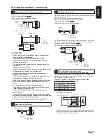
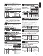
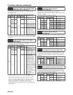
When connecting to the City Multi, Mitsubishi Electric Air-
Conditioner Network System (MELANS)
11
SW1: By-pass ventilation operation switch
:KHQFORVHG)RU%\SDVVYHQWLODWLRQRSHUDWLRQ
5HPRWHGLVSOD\DGDSWRU
2SWLRQDO3$&6$+$(
5HPRWHGLVSOD\DGDSWRU
2SWLRQDO3$&6$+$(
Brown 1
5HG
Orange 3
Yellow 4
Green 5
<HOORZ9'&
*UHHQ&20
Lossnay
control board
Lossnay
control board
Fan speed/
Ventilation
mode selection
Fan speed/
Ventilation
mode selection
External
device
Max wiring length 10 m
Max wiring length 10 m
2QHVKLHOGHGZLUHLVFRQQHFWHGWRWHUPLQDO7%
S
on the PCB.
$GGUHVVVHWWLQJLVUHTXLUHG5HIHUWRIXQFWLRQVHWWLQJVHFWLRQ
M-NET transmission cable: Connect any of the City Multi indoor
XQLWRU0LWVXELVKL(OHFWULF$LU
&RQGLWLRQHU1HWZRUN6\VWHP0(/$16
- to the Lossnay.
5HPRWH&RQWUROOHU
PZ-61DR-E:
Connect to TM4
1
2
on the PCB. (See Section
1
“When
FRQQHFWLQJZLWK5HPRWH&RQWUROOHU3='5(
”
6HFXUHO\FRQQHFWWKH01(7WUDQVPLVVLRQFDEOHVWR7%
AB
.
1R3RODU
7\SH6KLHOGHGZLUH&996&3(96
Wire diameter: 1.25 mm
2
to 2.0 mm
2
CAUTION
'RQ¶WWLJKWHQVFUHZVRQWKHWHUPLQDOEORFNZLWKDWRUTXHODUJHU
than 0.5 Nm. It may damage the PCB.
$OZD\VXVHVKLHOGHGZLUHVRQO\IRUWKH01(7WUDQVPLVVLRQ
FDEOHVDQG¿QLVKWKHVKLHOGSURSHUO\
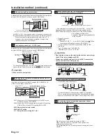
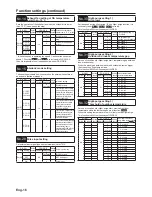
When interlocking with Mitsubishi M-NET air conditioner
,QFDVHRI3='5(
* Limit the total length of transmission cables no longer than
500 m. Limit the wiring length between Lossnay and the power
VXSSO\XQLW2SWLRQDORUWKHRXWGRRUXQLWQRORQJHUWKDQP
M-NET transmission cable
Lossnay
Power
supply unit
Lossnay
MELANS
M-NET transmission cable
Air
conditioner
Air
conditioner
MA remote
controller
When connecting to PZ-61DR-E and MELANS
&RQQHFWWKHSRZHUIHHGLQJXQLW
2SWLRQDO
3='5(
3='5(
L
N
PE
Switch
Isolator
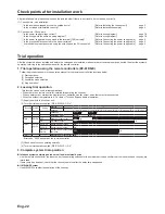
To start/stop Lossnay stand-alone operation without
using the remote control
12
Start/stop the unit by a switch connected to TM2
13
.
:KHQWXUQHGWKHXQLW21LWRSHUDWHVDWIDQVSHHGDQG
automatic ventilation mode.
Do not start/stop the unit by turning the power supply to the unit
ON/OFF.
TM2
TM1
CAUTION
0DNHVXUHRIFRUUHFWSRODULW\
Brown 1
5HG
Orange 3
Not used. Insulate completely.
Not used. Insulate
completely.
Lossnay external
control input


