


M a i n b o a r d
FT5000 HANDBOOK 5/11
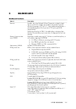
Memory
The memory module contains slots for 16 DIMMs and is attached to the mainboard through a
242-pin connector. Memory amounts from 128 MB to 4 GB of DIMM are supported, with a
64/72-bit four-way-interleaved pathway to main memory, which is also located on the module.
The 16 slots are divided into four banks of four slots each, labelled A to D. These banks support
4:1 interleaving. The memory controller supports EDO DRAMs. The four DIMMs in any bank
must be identical and preferably should be 60ns, each individual DIMM must be at least 32 MB.
The ECC used for the memory module is capable of correcting single-bit errors (SBEs) and
detecting 100 percent of double-bit errors over one code word. Nibble error detection is also
provided.
J16
J15
J12
J11
J8
J7
J3
J4
J14
J13
J10
J9
J6
J5
J1
J2
D
C
B
A
E
A.
Memory bank A (install first)
B.
Memory bank B (install second)
C.
Memory bank C (install third)
D.
Memory bank D (install last)
E.
Memory module connector
System memory begins at address 0 and is continuous (flat addressing) up to the maximum
amount of DRAM installed (exception: system memory is noncontiguous in the ranges defined as
memory holes using configuration registers). The system supports both base (conventional) and
extended memory.
Base memory is located at addresses 00000h to 9FFFFh (the first 1 MB).
Extended memory begins at address 0100000h (1 MB) and extends to FFFFFFFFh (4 GB),
which is the limit of supported addressable memory. The top of physical memory is a
maximum of 4 GB (to FFFFFFFFh).