


FUNCTION OVERVIEW
26
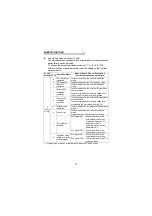
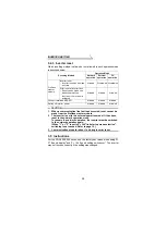
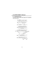
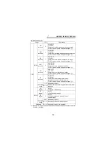
4.1.1 Input from master module to inverter
(1) Operation command
The following items can be output any time from the master module to
the inverter as operation commands. (Refer to pages 39, 46)
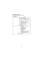
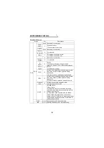
*1 These are factory-set signals. Input signals can be changed by input
terminal function selection (Pr. 180 and higher). Note that some signals do
not accept a command from the master module according to the settings.
Refer to page 15 for details. Signals to be assigned to input terminal
function selection (Pr. 180 and higher) differ according to the inverters. For
details, refer to the inverter manual.
*2 Signals can be assigned using input terminal function selection (Pr. 400 to
Pr. 402). Refer to page 8. (when the FR-A5NPA is connected)
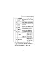
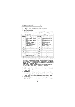
(2) Set frequency/set speed
Write a setting change from the master module to the inverter. (Refer
to pages 38, 45.)
(3) Parameter write
You can write a function from the master module. Note that writing a
function during inverter operation will result in a write mode error. (Refer
to pages 35, 42.) Refer to the inverter manual for parameter details.
(4) Inverter reset
You can reset the inverter or reset an inverter error. (Refer to pages
37, 44, 50, 60.)
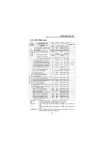
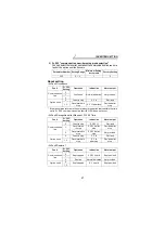
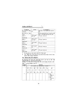
FR-A500/F500 series
FR-V500 series
Terminal
Operation Command
(Signal)
Terminal
Operation Command
(Signal)
STF
Forward rotation command
(STF)
STF
Forward rotation command
(STF)
STR
Reverse rotation command
(STR)
STR
Reverse rotation command
(STR)
RH
High speed operation
command (RH) *1
DI1
Low speed operation
command (RL) *1
RM
Middle speed operation
command (RM) *1
DI2
Middle speed operation
command (RM) *1
RL
Low speed operation
command (RL) *1
DI3
High speed operation
command (RH) *1
JOG
Jog operation selection (JOG)
*1
DI4
Second function selection
(RT) *1
RT
Second function selection
(RT) *1
DI11
— *2
AU
Current input selection (AU)
*1
DI12
— *2
CS
Instantaneous power failure
restart selection (CS) *1
DI13
— *2
MRS
Output stop (MRS)
MRS
Output stop (MRS)