14
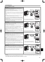
Clamps
Hold the wires in place
with clamps.
Main controller cable
See Step 5.
Wood screw
Thread the cable through the slot.
Completely seal the gap around
the cable access hole.
See Step 2.
Main controller cable
See Step 5.
Double switch box
Roundhead cross
slot screws
4. Electrical work
5. Install the back cover.
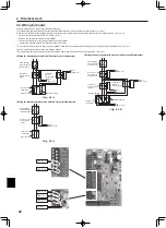
■ Installation using a switch box
• When installing the back cover in the switch box, secure at least two corners
of the switch box with screws.
<Fig. 4.2.>
■ Direct wall installation
• Thread the cable through the slot provided.
• When mounting the back cover on the wall, secure at least two corners of the
main controller with screws.
• To prevent the back cover from lifting, use top-left bottom-right corners of the
main controller (viewed from the front) to secure the back cover to the wall
with wall plugs or the like.
Caution:
To avoid causing deformation or cracks to the main controller, do not
overtighten the screws and make an additional installation hole(s).
6. Cut out the cable access hole.
■ Direct wall installation
• Cut out the knockout hole (indicated with grey in <Fig. 4.2.7>) in the cosmetic
cover by knife or nipper.
• Thread the main controller cable from the slot behind the back cover through
this access hole.
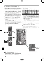
7. Plug the lead wire cable into the front cover.
Plug the lead wire cable coming from the back cover into the front cover.
Caution:
To avoid failures, do not remove the controller board protective sheet and the
controller board from the front cover.
After the cable is plugged into the front cover, do not hang the front cover
as shown in <Fig. 4.2.>. Otherwise, the main controller cable could sever,
which could cause malfunction to the main controller.
8. Fit the lead wires into the clamps.
Caution:
Hold the wires in place with clamps to prevent excessive strain from being
applied on the terminal block and causing cable breakage.
<Fig. 4.2.>
<Fig. 4.2.>
<Fig. 4.2.>
Securely plug the connector
into the jack.


