background image

English-40

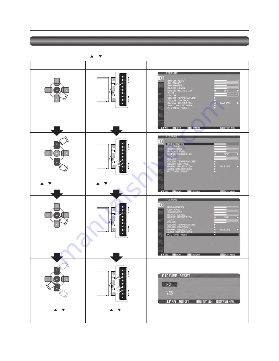
Basic operation of OSD

When the MENU button on the wireless remote control or the EXIT button on the monitor is pressed, the OSD screen is displayed.

Select a main menu by pressing the   or   button.

Accept the selected main menu 
by pressing the SET button.

Accept the selected main menu 
by pressing the INPUT button.

Select a sub menu by pressing 
the 

 or 

 button.

Select a sub menu by pressing 
the 

 or 

 button.

Accept the selected sub menu 
by pressing the SET button.

Accept the selected sub menu 
by pressing the INPUT button.

Select the setting value by 
pressing the 

 or 

 button 

and then press the SET button 
to accept the setting.

Select the setting value by 
pressing the 

 or 

 button and 

then press the INPUT button to 
accept the setting.

The OSD screen disappears when you press the MENU button on the wireless remote control once or the EXIT button on the 

monitor three times.

Wireless remote control

Monitor button

OSD screen

Confi guration and basic operation of OSD screen (continued)

Содержание BV013

Страница 1: ...lease be sure to read the Safety Precautions They are important to use this LCD display monitor Please check the content of the package This document contains instructions for World Wide model and Japan model but their accessories are different ...

Страница 2: ...onnection English 23 P 6 Connecting RS 232C English 25 Monitor control via RS 232C English 25 P 7 Connecting LAN English 26 Monitor connection using LAN English 26 P 8 Connecting the power cord to the monitor English 27 Connecting the power source English 27 How to Use English 28 Flow of How to Using English 28 U 1 Turning on all the connected devices English 29 Turning on external devices English...

Страница 3: ...personal computer Daisy chain Connection CAT5 Page 23 Linking up to 5 monitors You can connect up to 5 monitors in a daisy chain configuration using CAT5 cable max 200 meters The monitors can be installed away from each other depending on the usage Variable Management Functions Supporting Efficient Operation and Management Programmable Scheduling Function Pages 34 35 and 48 The monitor s operating...

Страница 4: ...Information 1 Use the attached specified cables with this equipment so as not to interfere with radio and television reception 1 The power supply cord you use must have been approved by and comply with the safety standards of U S A 2 Please use the supplied shielded video signal cable Use of other cables and adapters may cause interference with radio and television reception 2 This equipment has b...

Страница 5: ...ERVICEABLE PARTS INSIDE REFER SERVICING TO QUALIFIED SERVICE PERSONNEL This symbol warns user that uninsulated voltage within the unit may have sufficient magnitude to cause electric shock Therefore it is dangerous to make any kind of contact with any part inside this unit This symbol alerts the user that important literature concerning the operation and maintenance of this unit has been included ...

Страница 6: ...can be recycled and or reused This symbol means that electrical and electronic equipment batteries and accumulators at their end of life should be disposed of separately from your household waste If a chemical symbol is printed beneath the symbol shown above this chemical symbol means that the battery or accumulator contains a heavy metal at a certain concentration This will be indicated as follow...

Страница 7: ... LCD monitor is damaged and the liquid crystal leaks out do not inhale or swallow it Allow adequate ventilation around the monitor so that heat can properly dissipate Do not block ventilated openings or place the monitor near a radiator or other heat sources Do not put anything on top of the monitor The power cable connector is the primary means of detaching the system from the power supply The mo...

Страница 8: ...the cables Label to cover the UL certification marking Protective cover Wireless Remote Control and AAA Batteries Your LCD monitor MDT652S comes with the following For the use in the other regions use a power cord that matches the AC voltage of the power outlet and has been approved by and complies with the safety standard of those regions or countries The following components are supplied as opti...

Страница 9: ...tness function Reference Control Lock mode You can lock the operation buttons See page 51 1 Main Power Switch Switches the main power on off 2 Remote control sensor and Power indicator Remote control sensor Receives the signal from the wireless remote control Power indicator Indicates the state of the LCD monitor Steady green The power is on Steady red The power is off Some operations such as powe...

Страница 10: ...connector MINI DIN 4 pin VIDEO IN BNC connector VIDEO OUT BNC connector Connectors and Terminals L R R B H V G Cr Pr Cb Pb Y IN IN OUT OUT IN OUT 8 RGB6 IN DisplayPort Connects with the digital video output of a computer etc 9 RGB1 IN HDMI Connects with the digital video output of a computer DVD player etc 10 RGB OUT MINI D SUB 15 pin Outputs the signal that is supplied to the RGB3 RGB4 or RGB5 IN...

Страница 11: ...button Selects video to be displayed in the sub picture CHANGE button Changes the main picture with the sub picture Description PIP Picture in Picture The sub picture is displayed within the main picture POP Picture out Picture The sub picture is displayed to the bottom right of the main picture SIDE BY SIDE The main picture and the sub picture are displayed side by side NOTE When the screen size ...

Страница 12: ...Parts Name and Functions continued Installing and removing the Wireless remote control batteries The wireless remote control is powered by 1 5 V AAA batteries How to install the batteries 1 Unlock and pull up the cover in the arrow s direction 2 Align the batteries according to the and indications inside the case 3 Replace the cover How to remove the batteries 1 Unlock and pull up the cover in the...

Страница 13: ...witched 6 CAT5 OUT Modular connector 8 pin Connector for converting and outputting the video signal received by the RGB IN connector 3 and the control signal transmitted via the USB connector 1 or the RS 232C connector 2 to transmit them on the CAT5 cable CAUTION Never connect network devices to the CAT5 IN and OUT connectors If you do so they may adversely affect with each other causing breakdown...

Страница 14: ...g LAN Monitor connection using LAN Installing the monitor Using the wall mount or ceiling mount Using the monitor without the bezel Installing in the portrait position Pages 15 to 16 Page 17 Page 25 Page 26 Pages 18 to 22 Pages 23 to 24 Page 27 Page 28 Connection procedure Wiring diagram Prevention of disconnection of HDMI cable Connecting with a computer analog connection Connecting with a comput...

Страница 15: ... menu appears stop using the monitor and allow it to cool When the LCD monitor is used in an enclosure or with protection on LCD surface please check the inside temperature of the monitor by HEAT STATUS See page 50 If the temperature is higher than the normal level set COOLING FAN to ON using the SCREEN SAVER function See page 46 Install the monitor on a wall or ceiling strong enough to support it...

Страница 16: ...y and damage resulting from fall of the monitor in case of earthquake or other disaster be sure to consult the bracket manufacturer for installation location To lessen the risk of falling of the monitor thread commercially available rope through the handles at the right and left of the monitor and secure the rope to the wall mount brackets or ceiling mount brackets Do not sleep where the monitor m...

Страница 17: ...eration Environment Temperature shall be limited as shown below Operation Environment Temperature 5 35 C 41 95 F Humidity 20 80 without condensation Place the monitor in the position shown below Do not place the monitor in landscape in any other manner than shown Optional speakers can not be attached when the LCD monitor is installed in the portrait position How to set up The logo should be on the...

Страница 18: ...onitor falls Left speaker Right speaker Before connecting the signal cable to PC and Video Optional speakers can be installed Please refer to Quick Setup Guide of the optional speakers for the detailed installation procedure How to install the optional speakers 1 Use the metal fittings and screws supplied with the optional speakers For the installation procedure see the setup guide of the speakers...

Страница 19: ...onitor DVD player or HD disk player HDMI BNC VCR RCA Stereo amplifier External speakers Clamper Clamper Before making connections First turn off the power of all the connected equipment before making connections Refer to the user manual of each piece of equipment NOTE Please use the audio cable without resistance when the audio output terminal of the audio device and PC is stereo mini Jack When th...

Страница 20: ... commercially available to connect the mini D SUB 15 pin connector on the PC 2 Select RGB4 using the INPUT button on the monitor or the BNC button on the wireless remote control Second monitor connection Connect the RGB OUT connector mini D SUB 15 pin on the first monitor and the RGB3 IN connector mini D SUB 15 pin on the second monitor using a signal cable mini D SUB 15 pin mini D SUB 15 pin an a...

Страница 21: ... Connect an audio cable ø3 5 mm stereo mini commercially available to the AUDIO IN1 connector Select AUDIO1 using the AUDIO INPUT buttons on the wireless remote control When an HDMI cable is connected select HDMI audio You can select HDMI only when the video input is RGB1 Rear of LCD monitor P 4 Connection procedure continued The monitor automatically distinguishes the timings shown in the table b...

Страница 22: ...on the monitor use a BNC cable BNC x 3 BNC x 3 and a BNC RCA adaptor commercially available or a signal cable BNC x 3 D connector Select DVD HD using the INPUT button on the monitor or the YPbPr button on the wireless remote control To make audio connection connect an audio cable RCA to the AUDIO IN2 connector or the AUDIO IN3 connector Select AUDIO2 or AUDIO3 using the AUDIO INPUT buttons on the ...

Страница 23: ...to the S VIDEO IN connector select VIDEO S using the INPUT button on the monitor or the VIDEO S button on the wireless remote control To connect two monitors connect one end of a BNC cable to the VIDEO OUT connector of the first monitor and the other end to the VIDEO IN connector of the second monitor NOTE When different monitors need to be adjusted so that their tint can be identical such as when...

Страница 24: ...is unnecessary to install the USB driver if you don t use the communication control or the USB driver When the window asking you to install the driver is displayed select cancel As for the latest driver for the Windows operating system check the operation of the interface IC PL 2203 in advance referring to the website of Prolific Technology Inc Prolific Technology Inc and Mitsubishi don t assume a...

Страница 25: ...length and the defaults of all the adjustment values are automatically determined Select the length that is closest to the actual length of your cable 2 CAT5 EQ Make adjustment so that blur and smear of the displayed letters and graphic objects are minimized 3 CAT5 RED GAIN GREEN GAIN BLUE GAIN When the displayed image is dark increase each value When whites aren t displayed as intended adjust the...

Страница 26: ...r and this monitor using a reverse type RS 232C cable commercially available In addition when you connect two or more monitors as shown in the illustration below connect the RS 232C OUT connector of the first monitor and the RS 232C IN connector of the second monitor using a reverse type RS 232C cable commercially available By repeating the connection in the similar way you can connect monitors in...

Страница 27: ...ight type LAN cable commercially available When you connect two or more monitors you can connect the monitor and the LAN hub using a straight type LAN cable commercially available as described above CAUTION Do not connect the CAT5 IN or the CAT5 OUT connector to the LAN connector If connected both of the connectors may fail NOTE When you use a cross type LAN cable commercially available you can co...

Страница 28: ...e prongs into the power outlet socket Loose connection may cause noise NOTE Please refer to Safety Precautions Maintenance Recommended Use in this manual for proper selection of the AC power cord Use the clamper to prevent accidental disconnection of the power cord P 8 Connecting the power cord to the monitor Clamper Clamper Power cord For EU Power cord For North America ...

Страница 29: ... Page 33 Page 32 Page 33 Page 34 Pages 34 to 35 Pages 36 to 38 Turning on all the connected devices Selecting the video input Controlling the external devices Selecting the OSD language RGB3 RGB4 and RGB5 only Auto setup Selecting the picture mode Screen adjustment Picture adjustment Volume control Schedule setting Remote control How to Use ...

Страница 30: ...ndicator turns green Power Management Function This function reduces the power consumption of the monitor when the keyboard or the mouse is not used for a fixed period even though the power of the monitor is on While this function is working the screen becomes dark and the power indicator glows green and red This function is available only when a computer equipped with the VESA approved DPM Power ...

Страница 31: ...Pr VIDEO S and VIDEO Select using the INPUT button on the monitor When you press the INPUT button on the monitor the video input OSD menu is displayed and you can select the video input using the and buttons Selectable video inputs are RGB1 HDMI RGB2 DVI D RGB3 D SUB RGB4 BNC RGB5 CAT5 RGB6 DISPLAY PORT DVD HD VIDEO S and VIDEO NOTE The selection you make doesn t complete unless you press the INPU...

Страница 32: ...onnected devices to display images supplied from them U 4 Selecting the OSD language Select the OSD language using LANGUAGE in the CONFIGURATION1 menu of the OSD screen function See page 46 U 3 Controlling the external devices VCR etc Personal computer ...

Страница 33: ...black level NOTE The auto setup works on RGB3 RGB4 and RGB5 only U 6 Selecting the picture mode Using the PICTURE MODE button on the wireless remote control you can select the picture mode suitable for images to be displayed Auto setup or Displaying the OSD menu HIGHBRIGHT The brightness is maximized STANDARD Factory default setting sRGB Suitable for color matching with sRGB compliant devices CINE...

Страница 34: ...M horizontal resolution and vertical resolution NOTE The position adjustment works on RGB3 RGB4 RGB5 DVD HD VIDEO S and VIDEO only The clock adjustment and the resolution adjustment work on RGB3 RGB4 and RGB5 only The zoom adjustment works on all video inputs U 8 Picture adjustment You can adjust the picture by pressing the MENU button on the wireless remote control or the control buttons on the r...

Страница 35: ...rear of the monitor to display the OSD menu Using the AUDIO settings in the OSD menu you can adjust the balance treble and bass U 10 Schedule setting Carry out as necessary You can program the power on off and input selection using the SCHEDULE setting in the OSD menu that is displayed by pressing the MENU button on the wireless remote control or the control buttons on the rear of the monitor U 9 ...

Страница 36: ...time enter INPUT Set the video input to be selected when the power is turned on If you want to select the vide input that was selected before the power is turned on enter EVERY DAY Select this option to execute the schedule every day When you select EVERY DAY you cannot select any days of the week and EVERY WEEK MON SUN Select the days of the week on which you want to execute the schedule Unless y...

Страница 37: ...nt to connect multiple monitors or perform complicated control using other commands than the basic commands contact your dealer for advanced command specifications To use terminal software send a text file with control commands The monitor is not compatible with the sending of commands using a keypad Follow the same procedure for LAN control Address code Function code Data code End code HEX 30h 30...

Страница 38: ...ibed on the next page can be operated 5 Read command The computer sends the command without datacode to the monitor After receiving this command the monitor returns the command with datacode including the current status to the computer Example When the computer asks the power status of the monitor and the status of the monitor is powered on Command from computer Command from monitor Detail of comm...

Страница 39: ...me commands as those for RS 232C 1 Setting procedure 1 Set the following network parameters using the OSD menu See page 47 DHCP client ON OFF IP address subnet mask and default gateway 2 Set the IP address described above and the port number 63007 or 3007 using the application program of your computer to perform the socket communication 3 Send the same control command as that for RS 232C via TCP I...

Страница 40: ...ed out Sub menu screen When you select a sub menu an OSD screen is displayed Sub menus contain information screens adjustment menu screens and selection menu screens as shown below Sub menu screen Picture reset for example Page 41 Page 43 Page 44 Page 45 Page 46 Page 47 Page 49 Configuration of OSD screen This monitor is equipped with the OSD On Screen Display function for easy screen adjustment T...

Страница 41: ...essing the or button Accept the selected sub menu by pressing the SET button Accept the selected sub menu by pressing the INPUT button Select the setting value by pressing the or button and then press the SET button to accept the setting Select the setting value by pressing the or button and then press the INPUT button to accept the setting The OSD screen disappears when you press the MENU button ...

Страница 42: ... adjust all the colors at the same time Press the PLUS button to add a green tint Press the MINUS button to add a purple tint RED MAGENTA BLUE CYAN GREEN or YELLOW You can adjust each color individually Press the PLUS button to shift the selected color to the right around the color circle Press the MINUS button to shift the selected color to the left around the color circle COLOR For the RGB1 DVD ...

Страница 43: ...hen there is a light source such lighting equipment and a window behind the monitor NO Select this setting when there is no light source such lighting equipment and a window behind the monitor BACK WALL Select the following settings according to the distance between the rear of the monitor and the wall or window FAR The distance is 5 meters or longer NEAR The distance is 5 meters or shorter FRONT ...

Страница 44: ...ifferent magnifications at the screen center and the screen edges CUSTOM You can stretch the image horizontally and vertically as you desire using the CUSTOM ZOOM setting REAL The image is displayed without being stretched or reduced NOTE In the DYNAMIC mode the top and the bottom of the image may be cropped Full HD images are displayed as in the FULL mode CUSTOM ZOOM CUSTOM ZOOM becomes selectabl...

Страница 45: ...decrease the right volume TREBLE You can adjust the high frequency sound Press the PLUS button to increase the treble sound Press the MINUS button to decrease the treble sound BASS You can adjust the low frequency sound Press the PLUS button to increase the bass sound Press the MINUS button to decrease the bass sound AUDIO RESET You can reset all the AUDIO settings to the factory defaults ...

Страница 46: ... is output PIP H POSITION You can adjust the horizontal position of the sub screen Press the PLUS button to move the sub screen to the right Press the MINUS button to move the sub screen to the left PIP V POSITION You can adjust the vertical position of the sub screen Press the PLUS button to move the sub screen up Press the MINUS button to move the sub screen down SUB INPUT You can select the vid...

Страница 47: ...cooling fan always runs When you select AUTO the built in fan automatically starts running according to the operating temperature BRIGHTNESS When you select ON the brightness decreases MOTION The screen slightly moves horizontally and vertically at regular intervals to reduce the effect of the image persistence NOTE When you select a time period in the MOTION setting the monitor enlarges the image...

Страница 48: ...OFF Select this setting to configure the monitor as other than the one at the end of the connection when more than one monitor is multi connected LAN SETTING DHCP CLIENT Select whether to use DHCP client or not Select OFF when not using it and select ON when using it IP ADDRESS Set the IP address of the monitor SUBNET MASK Set the gateway mask Set it to 255 255 255 0 for normal use DEFAULT GATEWAY...

Страница 49: ...to make a selection If you create a schedule but do not want to set the power on time select in the ON time slot If you do not want to use a power off time select in the OFF time slot If there is no input selected showing in the input spot the input from the previous schedule will be used The selection of EVERY DAY within a schedule takes priority over other schedules that are set up to operate we...

Страница 50: ...MODE is AUTO set SCAN CONVERSION to PROGRESSIVE See page 49 IR CONTROL You can lock the wireless remote control Select from the following two modes using the and buttons and then determine the selected mode by pressing the SET button NORMAL All the remote control operations are enabled PRIMARY The first MDT652S monitor of those multi connected via RS 232C is designated as PRIMARY SECONDARY MDT652S...

Страница 51: ...at uses 16 to 235 levels of 256 levels for each of R G and B This mode is used primarily when input comes from a video device Select FULL when displaying the signal that uses all 256 levels from level 0 to 255 This mode is used primarily when input comes from a computer DDC CI Use to turn ON or OFF the DDC CI communication function Select ON for normal use CLOSED CAPTION You can select to display ...

Страница 52: ...ze Audio input change RGB1 HDMI AUDIO1 AUDIO2 AUDIO3 Other inputs AUDIO1 AUDIO2 AUDIO3 OSD information RGB2 1024 x 768 48kHz 60Hz AUDIO 1 SIZE FULL DVD HD AUDIO 3 SIZE FULL VIDEO S NTSC AUDIO 3 SIZE NORMAL RGB2 1024 x 768 48kHz 60Hz AUDIO 1 VIDEO S NTSC SIZE FULL Control Lock mode You can lock the operation buttons so that the image adjustments you made aren t changed even when the buttons are pre...

Страница 53: ... the monitors When using a computer to control the monitors you must prepare an application software program for control by yourself Brightness of all the monitors can be controlled centrally using a computer if the customer create a control application to remotely read the value from two brightness sensors of any monitor and distribute it to all monitors 1 Connect the RS 232C IN connector of the ...

Страница 54: ...pressing the PIP ON OFF button on the wireless remote control you can change the PIP POP and SIDE BY SIDE modes in the order shown below Alternatively you can change the modes using the PIP MODE setting of PIP in the OSD main menu See page 45 The resolutions in the PIP POP and SIDE BY SIDE FULL modes are as follows PIP SIZE SMALL 320 pixels X 240 pixels MIDDLE 480 pixels X 320 pixels LARGE 640 pix...

Страница 55: ...l sensor of the PRIMARY monitor OSD appears on the monitor having the ID number you selected NOTE When the ID selection OSD is being displayed on the PRIMARY monitor press the DISPLAY button on the remote controller again to cancel the ID selection OSD and then control the monitor you selected If you set the remote control mode wrongly and remote control operation becomes unavailable press any but...

Страница 56: ...ings may need to be re adjusted Check the monitor and your display card with respect to the compatibility and recommended signal timings If the displayed text is garbled change the video mode to the non interlace mode and use 60 Hz refresh rate Image of component signal is greenish Check to see if the DVD HD input connector is selected LED on the monitor is not lit No green or red color can be see...

Страница 57: ...B 15 pin PC AV Common Supported Resolution Composite Separate NTSC PAL SECAM 4 43 NTSC PAL60 Component Digital 480i 480p 576i 576p 1080i 720p 1080p Audio Input Output Input Connector Analog RCA pin jack L R x 2 Stereo mini jack Digital HDMI digital audio Output Connector RCA pin jack Speaker Output External Speaker Terminal L R 7W 7W 8 ohm Control Input Output Input Connector RS 232C D SUB 9 pin C...

Страница 58: ...t HDMI RGB1 Pin Assignment of HDMI connector 1 TMDS Data2 8 TMDS Data0 Shield 15 SCL 2 TMDS Data2 Shield 9 TMDS Data0 16 SDA 3 TMDS Data2 10 TMDS Clock 17 DDC CEC Ground 4 TMDS Data1 11 TMDS Clock Shield 18 5V Power 5 TMDS Data1 Shield 12 TMDS Clock 19 Hot Plug Detect 6 TMDS Data1 13 CEC 7 TMDS Data0 14 Reserved N C on device 4 Digital RGB input DVI D RGB2 Pin Assignment of DVI D connector 1 TMDS ...

Страница 59: ... 16 GND 7 ML_Lane 1 n 17 AUX CH n 8 GND 18 Hot Plug Detect 9 ML_Lane 1 p 19 Return 10 ML_Lane 0 n 20 DP_PWR 6 S VIDEO input MINI DIN 4 pin VIDEO S Pin No Name 1 GND 2 GND 3 Y Luminance 4 C Chroma 7 RS 232C input output LCD monitor CAT5 Tx BOX Pin No Name Pin No Name 1 NC 1 NC 2 RXD 2 RXD 3 TXD 3 TXD 4 NC 4 NC 5 GND 5 GND 6 NC 6 DSR 7 NC 7 NC 8 NC 8 NC 9 NC 9 NC 8 LAN Modular 8 pin Pin at RJ45 Sign...

Отзывы: