α
2 Simple Application Controllers
Function Blocks 6
6 - 58
Derivative Time and Derivative Gain, T
D
and K
D
.
D-control acts together with the
propor tional par t of PID-control. For changes in the PV, the Derivative component will
supplement the P-control depending on the rate of change of the PV. Derivative Control initially
outputs a large corrective action which dissipates rapidly over time. The outcome is that the PV
reaches the SV more quickly and does not fluctuate as much as with PI-control. There are two
ways to adjust the Derivative control of the PID Function Block, Derivative Time (T
D
) and
Derivative Gain (K
D
). T
D
can be set manually or automatically with the Auto-tuning function.
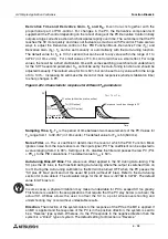
The default value for T
D
is 100 (1 second) but can be set to any value within the range of 1 to
32767 (in 10ms units). For small values of T
D
, D-control will have a small effect. For large
values, there will be a short stablization time with some searching (overshoot and undershoot)
for the SV. The second parameter, K
D
, cannot be set by the Auto-Tuning function and should be
adjusted manually. The default value for K
D
is 50% but can be set to any value within the range
of 0 to 100%. Increasing K
D
will make the D-control more responsive (shorter stablizaton time)
to sharp changes in PV.
Figure 6.22c. Characteristic response for different T
D
parameters
Sampling Time, T
S
.
T
S
is the period of time between two measurements of the PV. Values for
T
S
range from 1 to 32,767 (in 10ms units). The default value for T
S
is 50 (500 ms).
Noise Filter,
α
f
.
The
α
f
coefficient determines the level at which the PID Function Block
ignores noise from the input sensors on the input signal, PV. The coefficient can be adjusted to
a value ranging from 0 to 99%. Setting
α
f
to 0% disables the filter and passes the raw PV
(PV
n
= PV
nf
) to the PID calculations. The default value for
α
f
is 50%.
Auto-tuning Bias, AT Bias.
This value is an offset applied to the SV during Auto-tuning. The
SV, plus the AT bias, is the threshold during Auto-tuning where the output is switched from on
to off. During the Auto-tuning calibrations, the MV will be turned OFF when the PV passes the
“SV plus AT bias” point and not the usual SV point (without AT bias). Refer to the Auto-tuning
section for more details. The allowable range for the AT bias is -32768 to 32767. The default
value for AT bias is 0.
Note:
In some cases, a physical limitation may make it undesirable for PV to exceed SV too greatly.
This feature is useful in those applications that require that the PV stay below (or above) the
actual SV. AT-Bias allows the user to offset the SV to a point where overshooting and
undershooting may occur without undesirable results.
Direction.
The direction of the system refers to the response of the PV as the MV is applied. If
an MV is applied and the response of the PV is in the positive direction, the system is said to
be a “Reverse” type system. Whereas, if a the PV responds in the negative direction then the
system is a “Direct” type of system. The default setting for Direction is “Reverse.”
Time
Set value (SV)
PI action (without derivative action)
Response to sudden change in PV
T
D1
(PID action)
T
D2
(PID action)
T
D3
(PID action)
T
D3
> T
D2
> T
D1
PV

