background image


MITSUBISHI ELECTRIC 2033D SERIES UPS


MITSUBISHI 
ELECTRIC


2033D SERIES UPS 

OWNERS / TECHNICAL MANUAL


Page Number: 

2-11 


Terminals 33 to 34,    35 to 36 

"Minor Fault” contact (OUT8)


Activated when a minor fault has occurred to the system. 

Terminals 37 to 38,    39 to 40 

"Total Alarm” contact (OUT9)


Activated when an alarm, a minor fault, or a major fault has occurred to the 
system. 


NOTE:


The UPS is equipped with a selectable output contact feature. The above 

alarms are the default settings. Contact 

MITSUBISHI ELECTRIC 

AUTOMATION, INC.

 for setup information


B)    Input Contacts (for remote access of UPS) 

External contacts are provided by the user of the UPS system. Terminal voltage at the 
UPS is 24Vdc. Provide external dry contact accordingly.   


NOTE:


Do not apply voltages to remote access input terminals. Damage to UPS 

may result


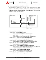
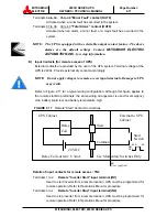
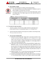
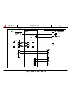
Refer to Figure 2.17 for a typical wiring configuration. Although this figure applies to 
the remote start/stop terminals, the same wiring arrangement is used for emergency 
stop; battery liquid low; and battery temperature high. 


FIGURE 2.17

    Remote "Start" Contact Connections   


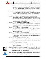
Details of input contacts for remote access : TN2


Terminals 1 to 2 

Remote "Inverter Start" input terminal (IN1)


Used to start inverter from a remote location. UPS must be programmed for 
remote operation. Refer to Operations Menu for procedure.   

Terminals 3 to 4 

Remote "Inverter Stop" input terminal (IN2)


Used to stop inverter from a remote location. UPS must be programmed for 
remote operation. Refer to Operations Menu for procedure. 

Start

Relay Coil current : 8.3mA

Use Momentary Switches Only

UPS Cabinet

External to UPS
Cabinet

Relay

Coil

24 VDC

Start

Switch

Common


User supplied


      0.5S    -    4S
ON 
OFF 

Содержание 2033D SERIES

Страница 1: ...MITSUBISHI ELECTRIC 2033D SERIES UPS MITSUBISHI ELECTRIC AUTOMATION INC UNINTERRUPTIBLE POWER SUPPLY SYSTEM 2033D SERIES OWNERS TECHNICAL MANUAL Revision 1 3 December 18 2003 ALN H0963 ...

Страница 2: ...23D_00s doc MITSUBISHI ELECTRIC 2033D SERIES UPS MITSUBISHI ELECTRIC 2033D SERIES UPS OWNERS TECHNICAL MANUAL Page Number i Preface ...

Страница 3: ...NDICATORS 2 1 2 1 LED DISPLAY 2 2 2 2 MBP LAMP 2 2 2 3 EPO BUTTON 2 2 2 4 LIQUID CRYSTAL DISPLAY 2 3 2 5 EXTERNAL SIGNAL TERMINAL BLOCK 2 8 2 6 EXTERNAL COMMUNCATION CONNECTOR 2 13 3 0 INSTALLATION AND OPERATION 3 1 3 1 TRANSPORTATION AND INSTALLATION 3 1 3 2 INSTALLATION PROCEDURE 3 1 3 3 PROCEDURE FOR CABLE CONNECTIONS 3 3 3 4 OPERATING PROCEDURES 3 12 3 5 MAINTENANCE BYPASS SET UP PROCEDURES 3 ...

Страница 4: ...on 1 11 Table 1 3 Detail of Specifications 1 12 Table 1 4 Rating of Contactor and Fuses 1 13 Table 3 1 How to Transport and Install the System 3 1 Table 3 2 List of UPS Weights lb 3 1 Table 3 3 Type and number of Battery 3 2 Table 3 4 Maximum Permitted Fault Current 3 3 Table 3 5 Recommended Cable Size and Torque Requirements 3 5 Table 3 6 Crimp Type Compression Lug 3 6 Table 6 1 Fault Code 6 2 ...

Страница 5: ...en 2 4 Figure 2 6 Measurement Screen 2 4 Figure 2 7 Setup Screen 2 5 Figure 2 8 Log Select Screen 2 5 Figure 2 9 Event Log Screen 2 5 Figure 2 10 Battery Log Screen 2 6 Figure 2 11 Main Screen Battery Operation 2 6 Figure 2 12 Measurement Screen Battery Operation 2 6 Figure 2 13 Main Screen Fault Indication 2 7 Figure 2 14 Message Screen 2 7 Figure 2 15 External Signal Terminal Block 2 8 Figure 2 ...

Страница 6: ...of this manual Warning A warning notice icon conveys information provided to protect the user and service personnel against hazards and or possible equipment damage Caution A caution notice icon conveys information provided to protect the user and service personnel against possible equipment damage Note A Note notice icon indicates when the user should make a reference of information regarding the...

Страница 7: ... manual contains descriptions required to operate the UPS Please read this manual carefully and retain it for future reference This manual contains important instructions for the 2033D Series Uninterruptible Power Supply System that should be followed during installation and maintenance of the UPS and batteries Lethal voltages exist within the equipment during operation Observe all warning and cau...

Страница 8: ...nstalled Recommended Breaker MCCB s Specifications are as follows Capacity kVA Bypass Voltage Vac Bypass Rating Aac Recommended Breaker Aac 30 480 36 45 50 480 60 80 80 480 96 125 AC input and AC output over current protection and disconnect devices shall be field supplied and installed DC output over current protection and disconnect device shall be field supplied and installed The over current p...

Страница 9: ...he orderly shutdown of equipment supported by the UPS The UPS is simple to start up operate and maintain The 2033D Series UPS is available in three 3 kVA sizes 30 50 and 80kVA and also in two 2 output voltages 208V and 480V Specifications for each kVA and voltage model appear in Section 1 4 30kVA model have batteries included in the UPS module cabinet 50 and 80kVA models have external batteries Th...

Страница 10: ...ry to convert input AC power to regulated DC power required for battery charging and for supplying power to the Inverter INVERTER The UPS components which contain the equipment and controls necessary to convert DC power from the Converter or the battery to AC power required by the critical load CHOPPER The UPS components which contain the equipment and controls necessary to charge the battery and ...

Страница 11: ...e path through the inverter is used to power the load Referring to Figure 1 1 Input AC power is converted to DC by the Converter DC power is utilized to charge the UPS battery and to provide power to the Inverter The Inverter converts the DC power to clean AC power to supply the critical load The conversion inversion process eliminates any voltage transients or fluctuations existing in the input p...

Страница 12: ...ritical load with unconditioned input power The purpose of this line is to route power to the critical load while the UPS module is de energized during Start up before the system is fully operational The internal control system determines the operation of the two paths with the load powered from the inverter being the normal operation UPS Module Power Flow Not in Use CB FB 72B 52RS CONVERTER INVER...

Страница 13: ... will power the inverter and critical load and simultaneously recharge the batteries A fully charged battery will provide power for the specified time at the rated load or longer at a reduced load When power is restored after a low battery shutdown the converter automatically restarts operation recharges the batteries and the Inverter is automatically restarted without operator intervention Load i...

Страница 14: ... Location 50kVA 80kVA 2 Grounding Bar 52C UPS module FRONT VIEW Inverter unit 72B 52CS 1 External I F Circuit PCB IOAU 05 Converter Unit 52RC Chopper Unit 52RS GND GND ELEC TERM DC Capacitor Parallel I F PCB 2 Grounding Bar 52RS UPS module FRONT VIEW Inverter unit 52RC 52CS 1 External I F Circuit PCB IOAU 05 Converter Chopper Unit 72B 52C GND GND ELEC TERM Parallel I F PCB ...

Страница 15: ...Number 1 9 FIGURE 1 5 UPS Parts Location Continued FIGURE 1 6 External I F PCB IOAU 05 UPS module BACKSIDE OF FRONT DOOR Right side FAULT RESET MAINTENANCE BUTTON TEST SWITCH BOOT SWITCH SYNC LED INVERTER START INVERTER STOP 8 7 9 10 5 6 IOAU 05 3 External Contact Signal Terminal 4 RS232C D sub Connector ...

Страница 16: ...me of asynchronous operation 6 INVERTER STOP Switch This switch is used to transfer the UPS from inverter to static bypass during maintenance purposes Do not operate it under normal operation Transfers will lock out if the bypass voltage is more than 10 10 of nominal Uninterrupted switching is made at the time of synchronous operation Switching is impossible at the time of asynchronous operation 7...

Страница 17: ...ications Rated output Power Input voltage 3 phase 3 wire Bypass input voltage 3 phase 3 wire Output voltage 3 phase 3 or 4 wire 30kVA 24kW 50kVA 40kW 80kVA 64kW 480V 480V 480V 480V 480V 480V 208V or 480V 208V or 480V 208V or 480V TABLE 1 2 UPS Module Information UPS kVA CABLE ENTRY WIDTH in mm DEPTH in mm HEIGHT in mm WEIGHT lb kg HEATING kBTU h 30 BOTTOM 33 9 860 31 5 800 70 9 1800 2060 930 9 1 5...

Страница 18: ... Voltage Stability 1 Frequency 60 Hz Frequency Stability 0 05 in free running mode Power Factor 0 8 nominal Power Factor range 0 8 1 0 lagging within output kW rating Voltage THD 2 typical THD at 100 Linear Load 5 typical THD at 100 non linear load Transient Response 3 at 100 load step 1 at loss return of AC power 3 at load transfer to from static bypass Transient Recovery 16 6ms Inverter Overload...

Страница 19: ...60A 100A 52RS Bypass Contactor 60A 100A 72B Battery Disconnect Contactor 80A 135A 200A C O N T A C T O R 88RC Control circuit Contactor 90A FIU FIV FIW Inverter Output Fuse 80A 660V 140A 660V FOU FOV FOW Inverter Output Fuse 80A 660V 140A 660V FUA FUB FUC Control Power Fuse 30A 600V FSU FSV FSW Option Bypass Input Fuse 140A 660V 280A 660V FBP FBN DC Input Fuse 125A 1250V 200A 1250V 350A 1250V FZS1...

Страница 20: ...ORS The 2033D Series operator controls and indicators are located as follows Circuit breakers and contactors Inside the module UPS status indicators Outside of front door FIGURE 2 1 Operation Display Panel Front panel LOAD ON INVERTER BATTERY OP LOAD ON BYPASS OVER LOAD LCD FAULT UPS FAULT EMERG STOP 1 2 6 3 5 4 9 8 MBP 540V 52RC 52C 72B STS 48A 7 ...

Страница 21: ... load devices by static bypass 4 Overload OVERLOAD red Illuminates in overload condition 5 LCD fault LCD FAULT red Illuminates when an error occurs 6 UPS fault UPS FAULT red Annunciater intermittent or constant tones Illuminates when an error occurs in the system In this case the details of the error are indicated on the display panel 2 2 MBP Lamp Maintenance Bypass Pilot Lamp 7 When operated in m...

Страница 22: ... LCD panel also allows the user to verify the status and operation of the UPS Module FIGURE 2 2 Main screen The following will be displayed when the START STOP key on the LCD panel is pressed 1 Start Stop screen FIGURE 2 3 The display indicates the start and stop operations for the UPS system If this operation is PIN protected the user is required to enter the security PIN before the screen can be...

Страница 23: ...tection screen FIGURE 2 5 Bypass voltage abnormal message screen f B MEASUREMENT MENU FIGURE 2 6 This screen shows details of measured values Bypass voltage input voltage output line to line voltage and output frequency are displayed Output currents are displayed as RMS values FIGURE 2 6 Measurement screen 52RC 52C 72B STS 52RC 52C 72B STS 540V 32kW 48A 48A 48A ...

Страница 24: ...attery equalizing charge The battery equalizing charge operation key will appear when battery equalizing charge is set up Setup is based on battery type FIGURE 2 7 Setup screen D LOG MENU FIGURE 2 8 This menu shows operation failure and battery discharge records FIGURE 2 8 Log select screen 1 Event log FIGURE 2 9 Operation and failure records are indicated Maximum of 50 events are displayed FIGURE...

Страница 25: ...screen FIGURE 2 12 Measurement screen Battery operation Battery operation The LCD will display a battery low voltage message when the battery capacity is near depletion The End of Battery Discharge announcement is displayed when the battery end voltage is reached At this time the inverter will perform an electronic shutdown to prevent battery loss of life typical from extreme deep discharge condit...

Страница 26: ...pressed 1 Message FIGURE 2 14 The display shows a fault code the description of the fault and a guidance of what action is to be taken by the user A maximum of 10 faults is displayed at one time If an input power failure occurs during a fault condition the fault indication and input power failure announcement are alternatively displayed at 5 second intervals FIGURE 2 14 Message screen 2 Silence al...

Страница 27: ...Figure 2 15 1 2 with a functional description of the input output port presented OUT1 to OUT9 are user programmable but factory default setting are shown in Figure 2 15 FIGURE 2 15 1 External Signal Terminal Block NEC Class2 TN1 UPS FAULT OUT2 LOAD ON INVERTER OUT3 BATTERY OPERATION OUT4 CONVERTER OPERATION OUT5 BATTERY LOW VOLTAGE OUT6 OVERLOAD OUT1 LOAD ON BYPASS 1 3 5 7 9 19 17 15 13 11 21 23 2...

Страница 28: ...IGH IN1 REMOTE INVERTER START IN2 REMOTE INVERTER STOP REMOTE EPO User supplied dry contact User supplied sensor and dry contact 1 3 5 7 9 19 17 15 13 11 21 23 25 27 29 2 4 6 8 10 20 18 16 14 12 22 24 26 28 30 IN4 POWER DEMAND User supplied dry contact IN5 ANOTHER UPS RECTIER OPERATION IN6 ASYNCHRONOUS IN7 CHARGE IL IN8 CHARGE RATE2 IN9 EQUALIZING UPS 52L AX 52C AX User supplied dry contact ...

Страница 29: ...major fault has occurred to the system Terminals 5 to 6 7 to 8 Load on Bypass contact OUT1 Activated when the power is supplied from the static bypass input Terminals 9 to 10 11 to 12 Load on Inverter contact OUT2 Activated when the power is supplied by the inverter Terminals 13 to 14 15 to 16 Battery Operation contact OUT3 Activated when the battery is operating following an AC power failure Term...

Страница 30: ...t apply voltages to remote access input terminals Damage to UPS may result Refer to Figure 2 17 for a typical wiring configuration Although this figure applies to the remote start stop terminals the same wiring arrangement is used for emergency stop battery liquid low and battery temperature high FIGURE 2 17 Remote Start Contact Connections Details of input contacts for remote access TN2 Terminals...

Страница 31: ...de The system is in asynchronous mode when the contact is closed and is in synchronous mode when the contact is open Terminals 13 to 14 Charger IL contact input IN7 This contact is used to control charging of the batteries When the contact is closed UPS will stop charging batteries When the contact is open UPS will start charging the batteries Terminals 15 to 16 Charge Rate 2 contact input IN8 Thi...

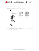
Страница 32: ...layout of connector is shown in Figure 2 18 FIGURE 2 18 External communication connector NEC Class2 Pin 1 Not used Pin 2 RXD Receive data Pin 3 TXD Transmit data Pin 4 Not used Pin 5 GND Signal ground Pin 6 Not used Pin 7 Not used Pin 8 Not used Pin 9 Not used Consult MITSUBISHI ELECTRIC AUTOMATION INC for details on DiamondLink monitoring software and its capabilities D SUB 9Pin male PCB IOAU 05 ...

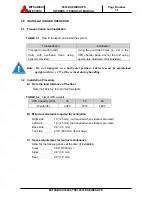
Страница 33: ...ansport in a horizontal position Cabinets must be maintained upright within 15 of the vertical during handling 3 2 Installation Procedure A Note the load tolerance of the floor Refer to Table 3 2 for list of UPS weights TABLE 3 2 List of UPS weights UPS Capacity kVA 30 50 80 Weight lb 2060 1810 1990 B Minimum clearance required for ventilation Right side 1 0 25 mm not required when sidecars are us...

Страница 34: ...0 50kVA 80kVA Note 50kVA and 80kVA UPS batteries are external to module cabinet Please refer to the remote battery supply installation manual 3 CAUTION Do not dispose of battery or batteries in a fire The battery may explode 4 CAUTION Do not open or mutilate the battery or batteries Released electrolyte is harmful to the skin and eyes and may be toxic 5 CAUTION A battery can present a risk of elec...

Страница 35: ...Wire per local and or national code iii Two 2 sources feeding the UPS 1 Connect the converter input power cables from the input service entrance to the converter input power terminals identified as A B C in Figures 3 2 a b Input cables must be sized for an ampere rating larger than the maximum input drawn by the converter Refer to equipment nameplate for current ratings Refer to Table 3 5 for reco...

Страница 36: ...s per Table 3 5 and referring to the appropriate figure identified in Figures 3 2 a b connect jumper bypass terminals A40 B40 C40 to converter input power terminals A B C as identified in Figures 3 2 a b 3 Referring to Figures 3 2 a b connect UPS load terminals A50 B50 C50 and N50 to the load distribution panel Refer to Table 3 5 for cable sizes 4 Connect the external signal terminal block as desi...

Страница 37: ...9 in lbs 4 AWG or larger 100 135 in lbs 3 AWG or larger 200 269 in lbs 1 AWG or larger 200 269 in lbs 50kVA 480V 208V 3 AWG or larger 200 269 in lbs 3 0 AWG or larger 347 469 in lbs 3 AWG or larger 200 269 in lbs 1 AWG or larger 200 269 in lbs 480V 480V 1 0 AWG or larger 200 269 in lbs 1 0 AWG or larger 200 269 in lbs 1 0 AWG or larger 200 269 in lbs 4 0 AWG or larger 347 469 in lbs 80kVA 480V 208...

Страница 38: ...46 1016 3 B B I BURNDY ILSCO BURNDY YA3C CRA 3L YA2C LB WHITE WHITE 9 9 1017 1 B B I BURNDY ILSCO BURNDY YA1C CRA 1L YA25 LB GREEN GREEN 11 375 11 375 1019 1 0 B B I BURNDY ILSCO BURNDY YA25 CRA 1 OL YA26 LB PINK PINK 12 348 12 348 1020 2 0 B B I BURNDY ILSCO BURNDY YA26 CRA 2 OL YA27 LB BLACK BLACK 13 13 1021 3 0 B B I BURNDY ILSCO BURNDY YA27 CRB 3 OL YA28 LB ORANGE ORANGE 14 101 14 101 1022 4 0...

Страница 39: ...A50 B50 C50 N50 AC Bypass Input AC input Terminals A40 B40 C40 Terminals A B C UPS Module FB 72B 52RS CONVERTER INVERTER 52C 52RC FI FO BATTERY Maintenance Bypass Switch Static Transfer Switch Output Terminals A50 B50 C50 N50 AC Bypass Input AC input Terminals A40 B40 C40 Terminals A B C UPS Module FB 72B 52RS CONVERTER INVERTER 52C 52RC FI FO Maintenance Bypass Switch Static Transfer Switch DC in...

Страница 40: ...s and terminal blocks Detailed Terminals H 70 9 1800mm D 31 5 800mm W 33 9 860mm AC input and Bypass input Terminals use 1 4 7mm Diameter bolts AC output and N50 Terminals use 5 16 9mm Diameter bolts UPS module UPS module AC Input A B C DC Input BN BP N50 AC Output A50 B50 C50 Bypass Input A40 B40 C40 External wiring block AC Output A50 B50 C50 Battery Input BN BP Bypass Input A40 B40 C40 AC Input...

Страница 41: ...Location of bus bars and terminal blocks Detailed Terminals H 70 9 1800mm D 31 5 800mm W 33 9 860mm AC input Bypass input AC output N50 and DC input Terminals use 7 16 11mm Diameter bolts DC Input BN BP N50 AC Output A50 B50 C50 UPS module UPS module External wiring block AC Output A50 B50 C50 Battery Input BN BP Bypass Input A40 B40 C40 AC Input A B C N50 AC Input A B C Bypass Input A40 B40 C40 ...

Страница 42: ...ES UPS OWNERS TECHNICAL MANUAL Page Number 3 10 FIGURE 3 3 Diagram of Power Wire Connect Parallel Connection AC Bypass Input AC input No 1 UPS Module AC input AC Bypass Input Battery cabinet Battery cabinet AC Output Parallel Cabinet 52L1 52L2 AC Input No 2 UPS Module ...

Страница 43: ...ire Control Wire Connect Parallel connection Critical Load Cabinet AC Output UPS 1 UPS 2 52L1 AX 52L2 AX TB1 UPS 2 A B C N A50 B50 C50 N40 N50 AC Output A B C N UPS 1 A50 B50 C50 N40 N50 AC Output Out Out B1 20 In In A2 10 Out A1 In B2 IFAU 01 Out Out A2 10 In In B1 20 Out B2 In A1 IFAU 01 IOAU 05 TN2 25 26 IOAU 05 TN2 25 26 1 2 3 4 3 4 1 2 16 ...

Страница 44: ...P OP LED will turn on and the UPS will transfer the load to the static bypass line WARNING Verify the load is OFF if the next step is to be performed NOTE Power to the critical load is supplied through the static bypass line Power to the critical load will be lost after execution of the next step The load will drop 2 If turning off all power to the critical load is desired open the AC Input Circui...

Страница 45: ...ine Also confirm that the BYP OP LED is on No 3 LED on Figure 2 1 3 After confirming Step2 rotate MBS 52CS clockwise to the TRANSFER position see figure 1 4 for the location of 52CS The MBP Lamp No 7 Lamp on Figure 2 1 will be illuminated Do not rotate MBS 52CS if the load is NOT fed by bypass source 4 After 3 seconds rotate 52CS clockwise to the BYPASS position 5 UPS can now be powered down 6 Tra...

Страница 46: ...uidance When a faults occur contact the Authorized Mitsubishi Service Representative or call Mitsubishi at 1 800 887 7830 UPS FAULT Annunciator Silence Recording of Fault Primary Action Information to Service Center Note The error code indicated on the LCD display panel at the time of a UPS alarm condition is very important In order to reduce repair time please include this information along with ...

Страница 47: ...average ambient operating temperature The end of battery life is defined as the state of charge resulting in an ampere hour capacity less than or equal to 80 of nominal capacity Replace battery if its capacity is within this percentage B UPS Component Parts Contact Mitsubishi or its Authorized Service Center for a complete parts replacement schedule Recommended replacement time interval varies wit...

Страница 48: ...ers fault codes their description and required action At time of error A Verify and record the occurrence of the alarm Note details of alarm message displayed on the LCD display panel Contact Mitsubishi Electric Automation Inc at 1 800 887 7830 B If a circuit breaker MCCB has tripped depress the toggle to reset the breaker before closing it again ...

Страница 49: ...or 36 hrs CALL SERVICE ENGINEER 2 Minor Flicker UF152 DC VOLTAGE ABNORMAL Does not return to equalizing voltage after power supply is resumed CALL SERVICE ENGINEER 2 Minor Flicker UF156 72B TRIPPED BATTERY OVERTEMP Battery temperature abnormality UF157 lasted a long time Note 5 CHECK BATTERY 2 Minor Flicker UF157 BATTERY OVERTEMPERATURE Battery temperature abnormality CHECK BATTERY 2 Minor Note 4 ...

Страница 50: ...R 1 Major Lit on UF303 UPS CONTROL CIRCUIT ERROR Control microcomputer abnormality CALL SERVICE ENGINEER 1 Major Lit on UF305 UPS CONTROL CIRCUIT ERROR Control clock abnormality CALL SERVICE ENGINEER 1 Major Lit on UF306 UPS CONTROL CIRCUIT ERROR Control power source circuit abnormality CALL SERVICE ENGINEER 1 Major Lit on UF309 INVERTER VOLTAGE ABNORMAL Inverter output voltage abnormality before ...

Страница 51: ...3 Alarm UA813 BYPASS PHASE ROTATION ERROR Phase rotation is inverted when bypass voltage is normal CHECK BYPASS INPUT 2 Alarm UA814 BYPASS FREQUENCY OUT OF RANGE Bypass frequency fell out of inverter synchronization follow up range CHECK BYPASS INPUT 3 Alarm UA817 EMERGENCY STOP ACTIVATED Emergency stop applied Alarm UA832 ASYNCHRONOUS TRANSFER Asynchronous transfer occurred 2 Alarm UA834 BATTERY ...

Страница 52: ...ne of two possible LED illumination patterns continuously on lit or intermittent flicker Note 4 External send out possible by option setting Note 5 Trips the battery breaker 72B Note 6 For other than sealed type battery Note 7 If the specified time elapses will transfer to the bypass power supply Note 8 Shows only when corresponding option settings are made Note 9 Code indication means UA Alarm UF...

Страница 53: ...ster your UPS for warranty purposes please complete the warranty registration form and fax it to the Mitsubishi Electric UPS Systems Group Service Department fax line shown on the registration form Next page For warranty purposes it is essential that any and all service work that may be required on your Mitsubishi brand UPS equipment is performed by a Mitsubishi Electric Authorized Service Center ...

Страница 54: ...known Signature Date Which ONE of These Best Describes Your Organization s Number of Employees at This Location is Primary Business Classification Energy Producer __ Education Univ Service __ 1 19 __ 100 249 __1000 or more __ Utility Service __ 20 49 __ 250 499 __ Alternate Energy __ Consulting __ 50 99 __ 500 999 Manufacturing Co __ Engineering __ OEM __ Outsourcing Overall how was Start Up perfo...

Отзывы: