14
6. WIRING METHOD
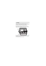
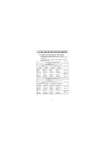
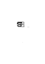
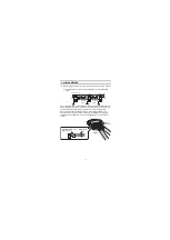
The following diagram shows how to wire the GOT and CC-Link system modules.
(1) Wiring the GOT and CC-Link system modules by CC-Link dedicated
cable
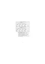
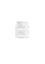
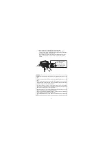
When connecting the CC-Link dedicated cables of the previous station and next
station, strip the wire sheaths off for 10mm (0.39 inch) and insert the cables into
the terminal block socket with every two wires in the same color together.
When connecting the braid shields of the CC-Link dedicated cables of the
previous station and the next station, caulk each braid shield to the supplied
solderless terminal (Plate type), then insert the shields into the terminal block
socket.
DA
DB
DG
SLD
FG
DA
DB
DG
SLD
FG
DA
DB
DG
SLD
FG
GOT
(Blue)
(Yellow)
(White)
Master module
I/O module, etc.
Terminal
resistor
CC-Link
dedicated
cable
CC-Link
dedicated
cable
Terminal
resistor
10mm
(0.39inch)
FG SLD
DG DB
DA
Braid
shield
Braid shield
Solderless terminal
(Plate type)
Next station
Previous station
Содержание 1D7M57
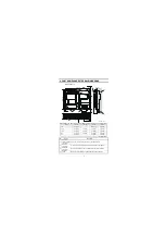
Страница 21: ...10 Extension interface relay board Unit mm inch 64 2 52 24 0 94 27 5 1 08 ...
Страница 27: ...16 MEMO ...

