1
ASSEMBLY INSTRUCTIONS
Unpacking Instructions
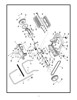
This unit is packed with a sidearm assembly and sidebroom inside the hopper. Refer to page 2 of
the Parts Manual for assembly and adjustment.
Operation
This unit works with two brushes the disc type sidebroom brings the dirt and waste from the side into
the path of the main broom. The main broom turns against the direction of the travel and throws the
dirt into the collection hopper. Both brushes are driven by the wheels. The main broom sweeps
forward while traveling forward and does not sweep in reverse. The sidebroom assembly will rotate
in both directions depending on forward or backward motion. The main broom assembly is a split
core design (Refer to page 4 Item #45 of the Parts Manual). When replacing broom assembly both
halves should be replaced together.
Adjusting Main Broom
Refer to page 3 of the Parts Manual for height adjustment information. The broom should be
adjusted so that the bristles just make contact with the surface to be swept. Increased brush
pressure to the surface
does not
enhance sweeping capability. Additionally, placing the
bristles too close to the surface will increase the forces needed to operate the machine and
may shorten the lift of the bristles.
Sidearm Assembly Adjustment
The sidearm assembly should be adjusted so that the bristles deflect slightly from the surface
to be swept.
Содержание Kleen Sweep 27 C89000-00
Страница 1: ...Model C89000 00 Kleen Sweep 27 Revised 8 02 OPERATION SERVICE PARTS CARE...
Страница 4: ...3...
Страница 5: ...4...


