


27
3) Connect the output wires of each UPS to an output breaker
panel.
4) Connect each output breaker to a main output breaker and
then to the loads.
5) Each UPS need an independent battery bank.
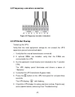
6) Please refer to the wiring diagram in the next page, and select
suitable breaker.
■
The output wiring requirement is as follows:
●
When the distance among the UPSs in parallel and the breaker
panel is less than 10 meters, the length difference between
input and output cable of the UPSs is required to be less than
20%.
●
When the distance among the UPSs in parallel and the breaker
panel is farther than 20 meters, the length difference between
input and output cable of the UPSs is required to be less than
5%.
4.6.3 Operation and maintenance
1) For normal operating, follow the single operating requirement.
2) Startup: The units transfer to INV mode simultaneously as they
start up sequentially in Line mode.
3) Shutdown: the units are shut down on INV mode in a sequent
way. When the last one completes the shutdown action, each
unit will turn off the inverter simultaneously and transfer to
Bypass mode.
Содержание 6-10KVA Tower
Страница 1: ...USER MANUAL ONLINE UPS 6 10KVA Rack Tower ...
Страница 24: ...21 Frequency converter without Bypass AC input ...
Страница 31: ...28 Figure 26 Parallel systerm wiring diagram of 6K 10K ...
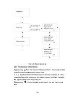
Страница 40: ...37 Fig 5 14 Main menu tree ...
Страница 47: ...44 Example set rated output voltage value Fig 5 22 Set rated output voltage value ...
Страница 61: ...58 614 08090 00 ...