background image

P-3

1-2.

Caution

WARNING

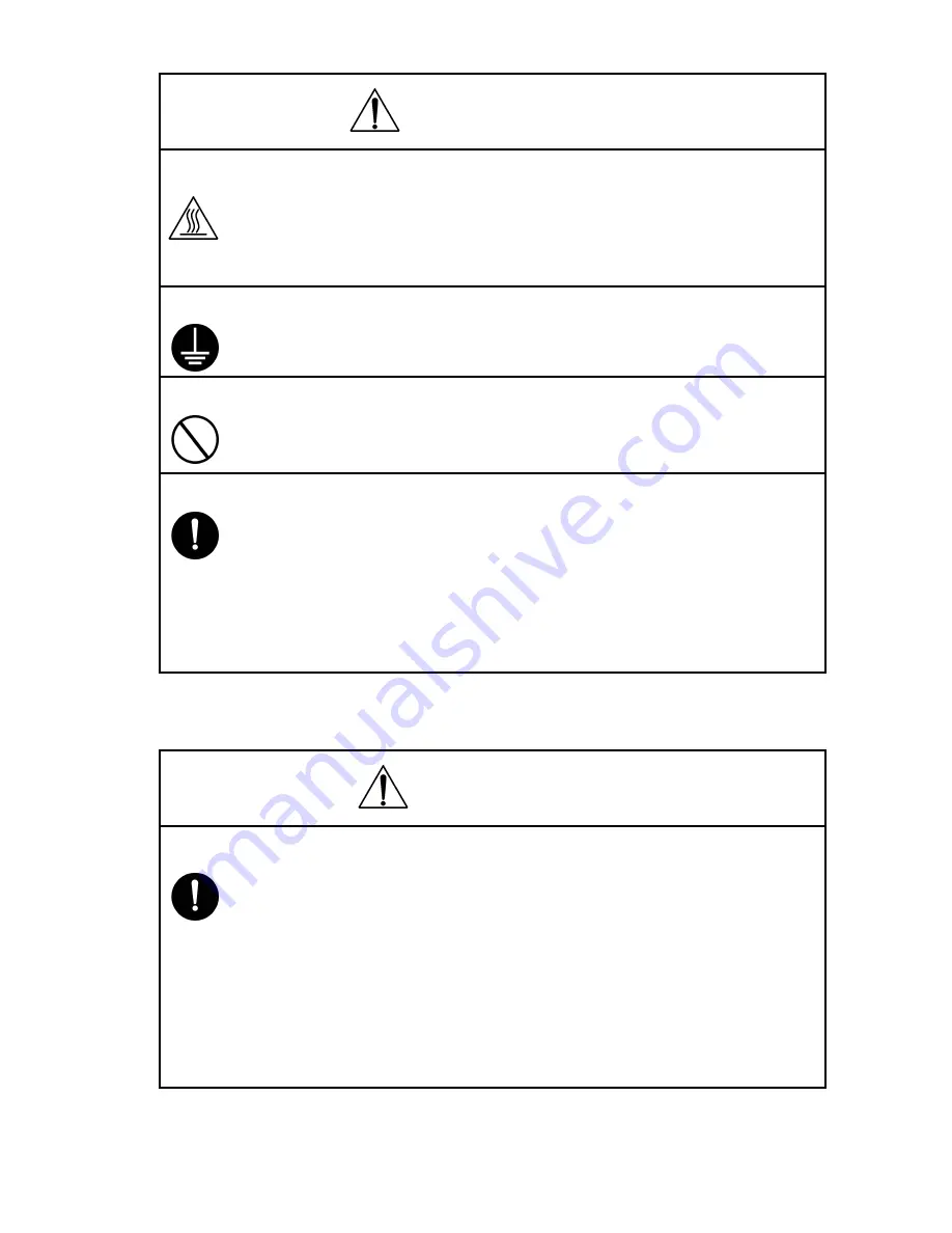
8. Do not touch a high-temperature part. 

• A part marked with the symbol shown on the left and other parts such as the 

exposure lamp and fusing roller can be very hot while the machine is ener-
gized. Touching them may result in a burn.

• Wait until these parts have cooled down before replacing them or any sur-

rounding parts.

9. Maintain a grounded connection at all times. 

• Connect the power cord to an electrical outlet that is equipped with a grounding 

terminal.

10. Do not remodel the product.

• Modifying this product in a manner not authorized by the manufacturer may 

result in a fire or electric shock. If this product uses a laser, laser beam leakage 
may cause eye damage or blindness.

11. Restore all parts and harnesses to their original positions.

• To promote safety and prevent product damage, make sure the harnesses are 

returned to their original positions and properly secured in their clamps and 
saddles in order to avoid hot parts, high-voltage parts, sharp edges, or being 
crushed.

• To promote safety, make sure that all tubing and other insulating materials are 

returned to their original positions. Make sure that floating components 
mounted on the circuit boards are at their correct distance and position off the 
boards.

CAUTION

1. Precautions for Service Jobs. 

• A star washer and spring washer, if used originally, must be reinstalled. Omit-

ting them may result in contact failure which could cause an electric shock or 
fire.

• When reassembling parts, make sure that the correct screws (size, type) are 

used in the correct places. Using the wrong screw could lead to stripped 
threads, poorly secured parts, poor insulating or grounding, and result in a mal-
function, electric shock or injury.

• Take great care to avoid personal injury from possible burrs and sharp edges 

on the parts, frames and chassis of the product.

• When moving the product or removing an option, use care not to injure your 

back or allow your hands to be caught in mechanisms.

Содержание Pi3505e

Страница 1: ...Pi3505e Pi3505e PS Service Manual ...

Страница 2: ...hibit the service technician from doing what is graphically represented inside the marking Used to instruct the service technician to do what is graphically represented inside the marking 1 1 Warning WARNING Indicates a potentially hazardous situation which if not avoided could result in death or serious injury CAUTION Indicates a potentially hazardous situation which if not avoided may result in ...

Страница 3: ...have a problem and action must be taken to eliminate the cause of the problem 5 Handle the power cord with care and never use a multiple outlet Do not break crush or otherwise damage the power cord Placing a heavy object on the power cord or pulling or bending it may damage it resulting in a possible fire or electric shock Do not use a multiple outlet to which any other appliance or machine is con...

Страница 4: ...ns and properly secured in their clamps and saddles in order to avoid hot parts high voltage parts sharp edges or being crushed To promote safety make sure that all tubing and other insulating materials are returned to their original positions Make sure that floating components mounted on the circuit boards are at their correct distance and position off the boards CAUTION 1 Precautions for Service...

Страница 5: ...de good ventilation at regular intervals if a service job must be done in a confined space for a long period of time Avoid dusty locations and places exposed to oil or steam Avoid working positions that may block the ventilation ports of the product 4 Precautions for Handling Batteries Lithium Nickel Cadmium etc Replace a rundown battery with the same type as specified in the manufac turer s parts...

Страница 6: ...r Mettre au rebut les batteries usagées conformément aux instructions du fabricant Denmark ADVARSEL Lithiumbatteri Eksplosionsfare ved fejlagtig håndtering Udskiftning må kun ske med batteri af samme fabrikat og type Levér det brugte batteri tilbage til leverandøren Finland Sweden VAROlTUS Paristo voi räjähtää jos se on virheellisesti asennettu Vaihda paristo ainoastaan laitevalmistajan suosittele...

Страница 7: ...o reassemble the product reverse the order of disassembly unless otherwise specified TROUBLESHOOTING If a component on a PWB or any other functional unit including a motor is defective the text only instructs you to replace the whole PWB or functional unit and does not give trou bleshooting procedures applicable within the defective unit All troubleshooting procedures contained herein assume that ...

Страница 8: ...use the GND wire 6 Handling of PWBs During Transportation Storage During transportation or when in storage new P W Boards must not be indiscriminately removed from their protective conductive bags Do not store or place P W Boards in a location exposed to direct sunlight and high tem perature When it becomes absolutely necessary to remove a Board from its conductive bag or case always place it on i...

Страница 9: ...um Do not apply chemicals to the surface of the PC Drum Do not attempt to wipe clean the surface of the PC Drum If however the surface is contaminated with fingerprints clean it using the following proce dure A Place the PC Drum into one half of its carton 1076D001 B Gently wipe the residual toner off the surface of the PC Drum with a dry Dust Free Cotton Pad Turn the PC Drum so that the area of i...

Страница 10: ...ionary Information on the PC Drum Inside the Imaging Cartridge and Print Unit Use care not to contaminate the surface of the PC Drum with oil base solvent finger prints and other foreign matter Do not scratch the surface of the PC Drum Do not attempt to wipe clean the surface of the PC Drum C Soak a small amount of either ethyl alcohol or iso propyl alcohol into a clean unused Dust Free Cot ton Pa...

Страница 11: ......

Страница 12: ... 2 1 CLAN circuit board M 3 DIS REASSEMBLY ADJUSTMENT 1 DISASSEMBLY REASSEMBLY D 1 1 1 Removing parts D 1 1 2 Checking the assembly D 8 DISPLAYS SETTINGS 1 CHECKING TOUCH PANEL DISPLAYS S 1 1 1 Printer controller Network interface unit S 1 2 CONTROLLER NETWORK SETTING S 2 3 SOFT SWITCH S 3 3 1 Changing soft switch settings S 3 3 2 Soft switch settings S 5 TROUBLESHOOTING 1 PROBLEMS WHILE PRINTING ...

Страница 13: ......

Страница 14: ...GENERAL MECHANICAL ELECTRICAL ...

Страница 15: ......

Страница 16: ... PS ROM 16MB Compact Flash Card Pi3505e 32MB Compact Flash Card Pi3505e PS RAM Additional 32 MB Pi3505e Additional 128 MB Pi3505e PS HDD 2 5 inch IDE interface Option Resolution 600 600 dpi Interface USB 1 1 10 100BaseT IEEE1284 Option Network Protocols TCP IP NetBEUI IPX SPX IPP SNMP HTTP EtherTalk Pi3505e PS only Operating Environmental Conditions Temperature 10 to 35 C Humidity 15 to 85 Font PC...

Страница 17: ...S Windows 98 Windows 98SE Windows Me Windows 2000 Windows XP Windows NT 4 0 Miscellaneous Should have sufficient memory and resources in the above Windows and other applications used Apple Macintosh Computers Pi3505e PS only CPU Power PC Memory 64MB or more OS Mac OS 8 6 9 2 or later Mac OS X 10 2 or later ...

Страница 18: ... USB connection 2 Network LAN interface Enables use as a network scanner and network printer through a connector for a network connection 3 Expansion PCI bus interface Equipped with a PCI bus interface connector specialized connector 100 pin for a future expansion interface Circuit Board Name Function Overview CLAN circuit board Enables use of network functions by connecting to the MFB3 board Prin...

Страница 19: ...not connected correctly Flashing Data is being sent or received Red Lit Operating at 100 Mbps Off Operating at 10 Mbps Address bus Data bus USB controller USB1 1b LAN controller Plus trans former LAN connector 8 pin 100base T USB connector 4 pin Series B PCI bus interface for future expansion Specialized 100 pin connector Europe PCI bus MFB3 board interface connector 100 pin C4514S004CA ...

Страница 20: ...DIS REASSEMBLY ADJUSTMENT ...

Страница 21: ......

Страница 22: ...e and printer functions 1 Removing the copier covers 1 Remove the upper rear cover 3 screws NOTENOTE While removing the cover be sure to press down on the detecting lever for the duplexing document feeder When attaching the cover make sure that the detecting lever fits into the hole in the upper rear cover 4399U008AB 2 Disconnect the 2 cable connectors 3 Remove the 2 cables from the cable clamp 4 ...

Страница 23: ... attaching the rear cover use 6 gold colored screws at the top 4599U009AB 4599U040AA 6 Remove the reinforcing plate 4 screws NOTE Make sure that the flat cable for the hard disk drive and the power relay harness are not pinched 4599U036AA 7 Remove the connector bracket 1 screw 4514U003AA ...

Страница 24: ...D 3 2 Removing the CLAN circuit board 1 If the hard disk drive kit is installed disconnect the connectors from CN4 and CN5 on the CLAN circuit board 4599U035AA 4599U034AA CN4 CN5 ...

Страница 25: ...CLAN circuit board C4514U008AA CLAN finger 4514U007AB CLAN circuit board Before installing the CLAN circuit board check that the OPE cable does not cover the connector for connecting the CLAN circuit board and then install the circuit board 4514U005AB When installing the CLAN circuit board press down at the two points indicated by arrows and then firmly insert the connectors Do not touch any solde...

Страница 26: ...3 circuit board 3 Remove the Network Scan circuit board or the Internet Fax Network Scan circuit board from expansion slot 2 CN5 of the MFB3 circuit board NOTE Do not touch the terminals of the printer circuit board with your bare hands When installing the printer circuit board check its installation direction location of the notch and then firmly insert the circuit board until it snaps into place...

Страница 27: ... for fax machines 4599U041AA 4 Remove the mechanical circuit board cover 5 screws NOTE Make sure that the harness on the right side of the mechanical circuit board cover is not pinched 4599U039AA 5 Disconnect the flat cable from the hard disk drive When connecting the flat cable to the hard disk drive align the cable with the side of the hard disk drive marked with and then connect the flat cable ...

Страница 28: ...circuit board tighten the bushing at the back of the mechanical circuit board until it appears as shown in the illustration 4599U022AA 4599U038AB 1 Remove the lower rear cover 4 screws NOTE During assembly place a toothed washer onto the screw in the upper right corner of the lower rear cover 4348U018AC 2 Disconnect the connectors from CN1 and CN2 on the power supply circuit board 4599U013AB 4599U...

Страница 29: ...work scan kit or Internet fax network scan kit Press the Utility key in the control panel touch Admin Management in the Utility screen appearing in the touch panel and then touch Admin 2 then Network Set and check that DNS Settings appears When specifying network settings the copier must be turned off then on again 3 Remove the power supply circuit board 4 screws 4599U012AA 1 Remove the ROM cover ...

Страница 30: ...DISPLAYS SETTINGS ...

Страница 31: ......

Страница 32: ...ng this option If the required options do not appear in the screens refer to the TROUBLESHOOTING section to correct the problem 1 1 Printer controller Network interface unit Checking that Printer Settings appears 1 Press the Utility key to display the Utility screen C4514P735CA Printer Settings is displayed ...

Страница 33: ...dress IP address of the controller Subnet mask Subnet mask for the network to be connected Default gateway IP address of the default gateway Check in advance with the network administrator on the setting values to be entered Turn the Power Switch OFF and then turn it ON This step is necessary to validate the data entered Starting PageScope Light This is the tool for making settings from the Web br...

Страница 34: ...e to turn the copier off then on again to quit the mode after specifying the necessary settings In order to ensure that the settings have been correctly specified check the Service Call Report that is outputted 1 Press the Utility key to display the Utility screen 2 Touch Meter Count 3 Press the following keys in order to enter Tech Rep Mode Stop 0 0 Stop 0 1 4 Touch Soft Switch Settings 5 In the ...

Страница 35: ... key to display the Utility screen 2 Touch Meter Count 3 Press the following keys in order to enter Maintenance Mode Stop 0 0 Stop 0 2 4 Touch Admin Management 5 Type in the administrator access code max 8 digits 6 Touch Admin 2 7 Touch Soft SW Set 8 In the screen that appears specify the soft switch settings ...

Страница 36: ...t1 are short the time for bits 7 through 0 of mode 432 wait time for computer printing with full memory M should also be short Note Features marked with asterisks can be specified by the user indicates screen settings Mode Factory Setting 320 7 6 5 4 3 2 1 0 Bit 0 0 1 1 0 0 1 1 HEX 33 Bit Feature Logical Value Description 0 1 7 4 Computer printing Around the clock monitoring timer t1 Bit 7 4 0000 ...

Страница 37: ...nd deter mines the communication speed Fixed at 100 Mbps Specifies a connection fixed at 100BASE TX Fixed at 10 Mbps Specifies a connection fixed at 10BASE T The settings are applied after the copier is turned off then on again 01 Fixed at 100 Mbps 10 Fixed at 10 Mbps 11 Do not specify this setting 5 Switching between full duplex and half duplex Specifies the packet transmission when connected to ...

Страница 38: ...f copy output bin Bin 1 Bin 2 Specifies the copy output bin when the job sepa rator is installed 1 Selection of fax G3 1 output bin Bin 1 Bin 2 Specifies the bin that fax G3 1 prints are fed into when the job separator is installed 0 Selection of output bin for computer printouts Bin 1 Bin 2 Specifies the bin that computer printouts are fed into when the job separator is installed Mode Factory Set...

Страница 39: ...her 5 1 Paper size set Bit 5 1 00000 A3 00001 B4 00010 1 A4 00011 B5 00100 A5 00101 B6 00110 A6 00111 Statement Invoice 01000 Exective 01001 2 letter 01010 Ledger 11x17 01011 FLS1 Folio F4 01100 FLS2 01101 FLS3 01110 FLS4 01111 Legal 8 5x14 10000 11x14 10001 envelope B5 10010 envelope Com10 10011 envelope C5 10100 envelope DL 10101 envelope Monarch 10110 J POST Hagaki 10111 Custom paper 11000 K16 ...

Страница 40: ... Portrait 01 Landscape 10 other 11 Not available 1 0 Select a print method to use when using PC printer function Bit 1 0 00 1 sided print 01 2 sided print for short edge binding 10 2 sided print for long edge binding 11 Not available Mode Factory Setting 442 7 6 5 4 3 2 1 0 Bit 0 0 0 0 0 0 0 1 HEX 01 Bit Feature Logic Description 0 1 7 0 Select last 8 bits of copies to print by PC printer Bit 7 0 ...

Страница 41: ...01111 Univers Medium Condensed 010000 Univers Bold Condensed 010001 Univers Medium Condensed Italic 010010 Univers Bold Condensed Itali 010011 Antique Olive 010100 Antique Olive Bold 010101 Antique Olive Italic 010110 Garamond Antiqua 010111 Garamond Halbfett 011000 Garamond Kursiv 011001 Garamond Kursiv Halbfett 011010 Marigold 011011 Albertus Medium 011100 Albertus Extra Bold 011101 Arial 011110...

Страница 42: ...1 001000 ISO 69 French 001001 ISO 8859 1 Latin1 001010 ISO 8859 2 Latin2 001011 ISO 8859 9 Latin5 001100 Legal 001101 Math 8 001110 Microsoft Publish 001111 1 PC 8 Code Page 437 010000 PC 8 Danish Norwegian 010001 PC 850 Multilingual 010010 PC 852 Latin2 010011 PC Turkish 010100 PS Math 010101 PS Text 010110 Pi Font 010111 2 Roman 8 011000 Ventura International 011001 Ventura Math 011010 Ventura U...

Страница 43: ... Logic Description 0 1 7 Select the unit of font size to use when using PC printer function Pitch Point 6 0 Fixed Do not change these settings Mode Factory Setting 448 7 6 5 4 3 2 1 0 Bit 0 0 1 1 0 0 0 0 HEX 30 Bit Feature Logic Description 0 1 7 0 Select font size to use when using PC printer function Scalable font size Last 8 bits Bit 7 0 00000000 5 00010000 4 00 16 00110000 12 00 48 11111111 Mo...

Страница 44: ...gic Description 0 1 7 6 Fixed Do not change these settings 5 0 Select font size to use when using PC printer function Bitmap font size First 8 bits Bit 5 0 000000 000011 10 00 1000 100110 99 00 9900 Others Not available Mode Factory Setting 452 7 6 5 4 3 2 1 0 Bit 0 0 0 0 0 0 0 0 HEX 00 Bit Feature Logic Description 0 1 7 Change between A4 and letter size for PC printing No Yes 6 0 Fixed Do not ch...

Страница 45: ...ic Description 0 1 7 0 Select timeout timer last 8 bits for PC printing Bit 7 0 00000000 Not available 00001001 00001010 10 sec 00001111 15 sec 00101100 300 sec 11111111 Not available Mode Factory Setting 456 7 6 5 4 3 2 1 0 Bit 0 0 0 0 0 0 0 1 HEX 01 Bit Feature Logic Description 0 1 7 1 Fixed Do not change these settings 0 Select timeout timer first 1 bit for PC printing 0 300 sec Most significa...

Страница 46: ...5535 Mode Factory Setting 467 7 6 5 4 3 2 1 0 Bit 0 0 0 0 0 0 0 0 HEX 00 Bit Feature Logic Description 0 1 7 5 Select frame type for PC printing Bit 7 5 000 Auto detect 001 Ethernet II 010 802 2 011 802 3 100 SNAP Others Do not specify these settings 4 0 Fixed Do not change these settings Mode Factory Setting 468 7 6 5 4 3 2 1 0 Bit 0 0 0 0 1 1 1 1 HEX 0F Bit Feature Logic Description 0 1 7 Settin...

Страница 47: ......

Страница 48: ...TROUBLESHOOTING ...

Страница 49: ......

Страница 50: ...to this there may be slight errors in the hori zontal and vertical direc tions These errors differ depending on the paper 2 Only some of the pages were printed or the data for one page was printed on two pages The binding margin is incorrect Check the print area 3 The left side of the page is blank The text is only printed on the right side of the paper The paper position shifted Correctly load th...

Страница 51: ...on the data for mat blank pages may not be output ted 6 When the document is reduced the print result differs from the docu ment before it was reduced With this unit reduced printing is performed by reducing coordinates At that time round off errors may occur in the values and the print result may appear different due to changes in the data such as overlapping images Num ber Symptom Possible Cause...

Страница 52: ...rrect Check the print port on the Ports tab Windows 2000 XP NT 4 0 or General tab Windows 98 Me This unit is not selected as the default printer Select this unit as the default printer The print queue is temporarily paused or is offline Continue the queue or set the copier online 8 No paper is fed out There is no paper or there is no paper of the specified size If a message appears indicating that...

Страница 53: ...rientations 12 The paper size cannot be specified If booklet binding is specified paper larger than A4 post cards and enve lopes cannot be specified Check if the Book let Creation set ting is selected Depending on the Finish ing setting that is selected the paper size cannot be specified 13 The paper size is not as specified Depending on the application the paper size specified from the printer s ...

Страница 54: ...ce speci fied from the printer s Properties dialog box is not applied Specify the paper source by using the Print command in the application The paper source can be specified both from the printer s Properties dia log box and by using the Print command in most applications however depending on the applica tion the paper source selected from the printer s Properties dialog box may not be applied Pa...

Страница 55: ...nding on the applica tion sorting selected by using the Print command may result in any of the following If double sided printing is selected the first page of the n 1 set is printed on the reverse side of the last page of the n set If booklet binding is specified all pages are printed and combined into one set If stapling is selected all pages are stapled together as one set If the Distribution f...

Страница 56: ...g docu ment feeder is not selected on the Device Options Set ting tab Check that the duplexing docu ment feeder is installed and check the selected settings on the Device Options Setting tab In order to specify double sided printing the optional duplexing docu ment feeder must be installed In addition dou ble sided printing cannot be specified unless the duplexing document feeder is selected on th...

Страница 57: ...oklet binding the optional duplexing document feeder must be installed In addition booklet bind ing cannot be specified unless the duplexing doc ument feeder is selected on the Device Options Setting tab 24 Booklet bind ing is not performed as specified The paper size of each page is differ ent Check the paper size If multiple copies are not printed correctly with booklet binding refer to the info...

Страница 58: ...her and saddle kit are selected on the Device Options Setting tab Postcards or enve lopes are selected as the paper size The paper is being supplied manually Booklet binding is specified Overhead projec tor transparency interleaving is specified with the Cover Mode or OHP Interleav ing function Check the paper type paper size and paper source settings and check if the Book let Creation set ting or...

Страница 59: ...setting and check if the Book let Creation set ting or the OHP Interleaving func tion is selected 30 Stapling is not per formed as specified Thick paper or over head projector trans parencies are used Check the paper type The number of copies exceeds 50 pages Paper with differ ent sizes are com bined Check the number of copies and the paper size Stapling will be par allel to the paper feed directi...

Страница 60: ...s and cover pages with the same orientation and size as the document 33 Distribution numbering cannot be specified If sorting is not spec ified distribution numbering cannot be selected Check that sorting is selected 34 Distribution numbering is not per formed as specified After specifying the distribution number sorting was can celled Check that sorting is specified Depending on the selected sett...

Страница 61: ...on the documents stored in the unit s memory except with copies and computer printouts 2 2 Warm restart procedure Press the button in the small hole on the side of the control panel 2 3 Warm restart operation The warm restart operation begins when the operation described in 2 2 is performed At this time the touch panel goes off After approximately 5 seconds the warm restart operation is completed ...

Страница 62: ...7662 4513 11 Copyright 2003 MINOLTA CO LTD MINOLTA Co Ltd Use of this manual should be strictly supervised to avoid disclosure of confidential information ...

Отзывы: