background image

10

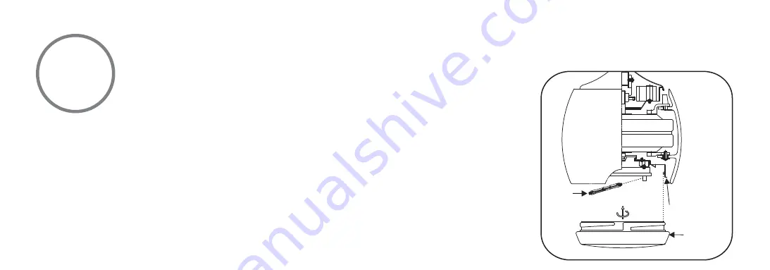
Fig. 16

        WARNING: Shut off the power supply before removing or replacing lamp. In handling of    

halogen bulb, care should be taken not to touch it with your bare hands. Oil residue will shorten 

the life of the halogen bulb. If you accidentally come into contact, wipe thoroughly with a clean, 
lint-free, cotton cloth. Allow the bulb to cool off for 10 minutes before changing the bulb. Use light 
bulb in accordance with the fan's specification. TO REDUCE THE RISK OF FIRE DO NOT EXCEED 
MAXIMUM WATTAGE  RATING.

Step 1. Install 80W R7S halogen globe (included). (Fig. 16) (Disregard this step if using the optional 

switch cup cover)

Step 2. Raise glass shade or optional switch cup cover up against bottom of fan housing and secure 

it to fan by turning it clockwise until snug. DO NOT OVERTIGHTEN. (Fig. 16)

Note: If installing the optional metal switch cup cover, make sure it is securely tightened.

INSTALLING THE LIGHT GLOBE & GLASS SHADE 

GLOBE

LIGHT PLATE

GLASS SHADE 

OR OPTIONAL

SWITCH CUP

COVER

Содержание Artemis F803

Страница 1: ...by INSTRUCTION MANUAL WARRANTY CERTIFICATE U S Patents D535 011 D535 015 D535 387 D535 388 D536 083 7 481 626 Model No CRYSTAL F 803 ...

Страница 2: ...T PLATE INSTALLING THE LIGHT GLOBE GLASS SHADE CARE OF YOUR FAN TROUBLESHOOTING SPECIFICATIONS 1 2 3 4 5 6 7 8 9 10 1 1 12 13 SAFETY RULES PACKAGE CONTENTS INSTALLING THE FAN HANGING THE FAN ELECTRICAL CONNECTIONS FINISHING THE INSTALLATION BLADE INSTALLATION ...

Страница 3: ...motor hum and cause damage to the motor Only use the wall controller supplied 6 It is not recommended that ceiling fans and gas appliances be operated in the same room at the same time 7 To prevent damage the fan must be turned off and stopped completely before reversing the fan direction 8 Do not insert anything into the fan blades while the fan is operating as this may cause injury damage the bl...

Страница 4: ...CLEANING THE FAN DO NOT INSERT FOREIGN OBJECTS BETWEEN ROTATING FAN BLADES TO REDUCE THE RISK OF FIRE OR ELECTRONIC SHOCK THIS FAN ONLY CAN USE WERFL WALL CONTROL ONLY NOTE READ AND SAVE ALL INSTRUCTIONS NOTE The important safeguards and instructions appearing in this manual are not meant to cover all possible conditions and situations that may occur It must be understood that common sense caution...

Страница 5: ... plate 10 Glass shade 11 Optional switch cup cover 12 80W R7S halogen bulb A Mounting hardware 10 x 1 5 Wood screws 2 PCs 8 x 3 4 Machine screws 2 PCs Lock washers 2 PCs 4mm Star washers 2 PCs Wire nuts 3 PCs Washers 2 PCs B Bracket holder hardware 3 16 x 17mm Screws with lock washers 10 PCs PACKAGE CONTENTS 1 Unpack your fan and check the contents You should have the following items 5a 5b 2 12 4 ...

Страница 6: ...weight of the fan at least 50 lbs Use a safety approved metal outlet box Do not use a plastic outlet box Figure 1 2 and 3 are examples of different ways to mount the outlet box Note You may need a longer downrod to maintain proper blade clearance when installing on a steep sloped ceiling Longer downrods are available from your dealer of MR KEN FIG 1 FIG 3 FIG 2 FIG 4 CROSS BRACE CEILING JOIST CEIL...

Страница 7: ...the top coupling of the motor assembly Fig 6 Step 3 Remove hanger ball from downrod assembly by loosening set screw removing the cross pin and sliding ball off rod Fig 7 Step 4 Carefully feed fan wires up through the downrod Fig 8 Thread the rod into the coupling next line up holes and replace lock pin and hitch pin Tighten set screws Step 5 Slip coupling cover canopy cover and canopy onto downrod...

Страница 8: ... 6 Fig 10 Fig 9 CANOPY COVER OUTLET BOX HANGER BRACKET DOWNROD SUPPLY WIRES REGISTRATION SLOT CROSS PIN HANGER BALL DOWNROD HITCH PIN LOCK PIN SET SCREWS SET SCREW DOWNROD CANOPY SET SCREWS HITCH PIN LOCK PIN COUPLING COVER ...

Страница 9: ...ctions are tight including ground and that no bare wire is visible at the wire connectors except for the ground wire Do not operate fan until the blades are in place Noise and fan damage could result 2 Installing Wall Control With electrical power still disconnected remove the existing wall plate and switch Make wiring connections to terminal block as shown in Figure 11 Brown wire from wall contro...

Страница 10: ...GHT 220 240 VAC SUPPLY User Supplied YEL GRN from fan YEL GRN from bracket ORN TO LIGHT BRN TO MOTOR BLUE NEUTRAL BRN TO HOT BLUE NEUTRAL BRN HOT YEL GRN EARTH Wall Control Rear View Terminal Block on Hanger Bracket L L1 N L L1 N ...

Страница 11: ...ver the screw on the hanger bracket turn canopy until it locks in place at the narrow section of the key holes Fig 12 Step 3 Align the circular hole on canopy with the remaining hole on the hanger bracket secure by tightening the two set screws Note Adjust the canopy screws as necessary until the canopy and canopy cover are snug FINISHING THE INSTALLATION Fig 12 OUTLET BOX HANGER BRACKET HANGER BA...

Страница 12: ...oles from the lower blade holder Secure blade with 3 screws provided Follow the same process for the remaining two blades Fig 13 All blade sets are grouped together by weight Because plastic materials vary in density the fan may wobble even though the blades are weight matched BLADE INSTALLATION BLADE LOWER BLADE HOLDER SCREWS UPPER BLADE HOLDER TABS ...

Страница 13: ...les from the mounting plate over the 2 screws previously loosened from the mounting ring turn mounting plate until it locks in place at the narrow section of the key holes Secure by tightening the 2 screws previously loosened and the one previously removed Fig 14 INSTALLING THE MOUNTING PLATE MOUNTING RING SCREWS MOUNTING PLATE ...

Страница 14: ...ise and hold the light plate close to the mounting plate and proceed to do the wire connections Connect the white wire connectors from the light plate and fan follow the same procedure with the black wire connectors Fig 15 3 Install and Secure the light plate by tightening the 3 screws previously removed Fig 15 INSTALLING THE LIGHT PLATE SCREWS LIGHT PLATE CONNECTORS MOUNTING PLATE ...

Страница 15: ...ht bulb in accordance with the fan s specification TO REDUCE THE RISK OF FIRE DO NOT EXCEED MAXIMUM WATTAGE RATING Step 1 Install 80W R7S halogen globe included Fig 16 Disregard this step if using the optional switch cup cover Step 2 Raise glass shade or optional switch cup cover up against bottom of fan housing and secure it to fan by turning it clockwise until snug DO NOT OVERTIGHTEN Fig 16 Note...

Страница 16: ...er operation Slide the switch to the Right for cool weather operation Fig 17 Warm Weather forward A DOWNWARD airflow creates a cooling effect as shown in Figure 18 This allows you to set your air conditioner on a warmer setting without affecting your comfort Cool Weather Reverse An UPWARD airflow moves warmer air off the ceiling area as shown in Figure 19 This allows you to set your heating unit o...

Страница 17: ... mode Warm Weather forward A DOWNWARD airflow creates a cooling effect as shown in Figure 18 This allows you to set your air conditioner on a warmer setting without affecting your comfort Cool Weather Reverse An UPWARD airflow moves warmer air off the ceiling area as shown in Figure 19 This allows you to set your heating unit on a cooler setting without affecting your comfort SUMMER OPERATION WINT...

Страница 18: ... 3 If your fan is provided with wood veneer blades you can apply a light coat of furniture polish for additional protection and enhanced beauty Cover small scratches with a light application of shoe polish 4 Use a lint free lightly damp cloth or duster to remove dust from the blades 5 There is no need to oil your fan The motor has permanently lubricated bearings 6 If your fan is provided with glas...

Страница 19: ...to make sure all screws in motor housing are snug not over tight 3 Check to make sure the screws which attach the fan blade holders to the motor flywheel are tight 4 Check to make sure wire connectors in switch housing are not rattling against each other or against the interior wall of the switch housing CAUTION Make sure main power is turned off 5 Some fan motors are sensitive to signals from sol...

Страница 20: ...t 4 Check to be sure the fan blade holders seat firmly and uniformly to the surface of the motor housing If holders are seated incorrectly loosen the screws and retighten 5 Tighten the hanger bracket screws to the outlet box and secure outlet box 6 Interchanging position of fan blades can redistribute the weight and result in a smoother operation For example exchange blades in positions 1 and 3 or...

Страница 21: ...d Volts Amps Watts Low Medium High SPECIFICATIONS These are typical readings Your actual fan may vary They do not include amps and wattage used by the light s for reference only 0 14 0 24 0 30 13 42 68 68 110 133 3100 5900 8000 3 96 11 57 Kgs 13 50 Kgs ...

Страница 22: ...by Distributed By BRAIN THAI ENTERPRISE CO LTD E mail info mrken fan com www mrken fan com ...

Отзывы: