background image


miniDSP Ltd, Hong Kong / 

www.minidsp.com

 / Features and specifications subject to change without prior notice


24 

4.4.4


Custom System configuration 

On the Sound System tab, choose the Custom System configuration if any of the following apply: 


Your system does not fit any of the three predefined configurations (Stereo, 5.1, 7.1). 


You want to use a different channel mapping than the default. 


You do not want the nanoAVR DL to calibrate for a 10 dB LFE alignment gain on the subwoofer channel. (LFE 
alignment gain is used to compensate for the reduced level of the LFE track as it is recorded to movie 
soundtracks. For almost all home theater applications, 5.1 or 7.1 is the correct choice. Custom configuration 
should be used only in special circumstances.) 


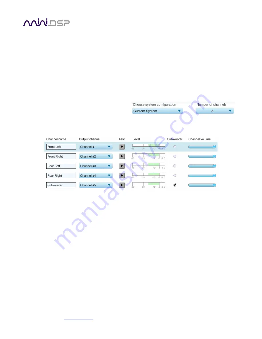
After choosing Custom System, you will need to 
select the number of channels that you want to use.  


When you get to the Output & Levels tab, it will show controls for the number of channels that you selected: 


Channel name 


Type any name you like for each channel. 

Output channel 


By default, each input channel maps to the same numbered output channel (input channel 1 to 
output channel 1, and so on). The dropdown selectors can be used to change this mapping. Note 
that DLCT will not let you assign more than one output channel to each input channel. 


If your custom system configuration has less than eight channels, inputs are assigned in 
sequential order. For example, for a 4.1 channel system, channels 1 through 5 are used. 

Subwoofer 


The subwoofer checkbox tells the Dirac Live analysis algorithm to use a different method to 
detect the impulse on that channel, which in turn affects the delay that will be assigned to that 
channel. This is needed because of the limited frequency response of the subwoofer. 


Содержание Home Theater Series

Страница 1: ...DSP Ltd Hong Kong www minidsp com Features and specifications subject to change without prior notice 1 Home Theater Series NANOAVR DL 8 CHANNEL HDMI AUDIO PROCESSOR WITH DIRAC LIVE TECHNOLOGY User Man...

Страница 2: ...iguration smartphone app channel mode 19 May 2015 1 2 Updated firmware update procedure 20 May 2015 1 3 Updated for Mac version of software 11 July 2015 1 4 Updated Output Levels tab 16 July 2015 1 5...

Страница 3: ...3 3 2 Installation Windows 14 3 2 1 Possible Windows installation issues 14 3 2 2 nanoAVR DL Utility installation 14 3 2 3 Dirac Live Calibration Tools DLCT installation 14 3 3 Installation Mac OS X 1...

Страница 4: ...ning your target curve 32 5 3 1 The Auto Target 32 5 3 2 Editing the target curve 32 5 3 3 Changing the frequency range for correction 32 5 3 4 Guidelines for target curve design 33 5 3 5 Saving and l...

Страница 5: ...use or incorrect configuration of this product Please read this manual carefully to ensure that you fully understand how to operate and use this product as incorrect use or use beyond the parameters a...

Страница 6: ...t into an outlet on a circuit different from that to which the receiver is connected Consult the dealer or an experienced radio TV technician for help Notice Shielded interface cable must be used in o...

Страница 7: ...nd selected from the front panel by an infrared remote control not included or a smartphone control app Video from the selected input is switched directly to the output with no processing applied to t...

Страница 8: ...d to imprecisely as frequency response In contrast to fully automated systems Dirac Live corrects the magnitude response towards a user adjustable target response The target response takes account of...

Страница 9: ...heir impulse response characteristics neither can make a desired change to the magnitude response independently of controlling the impulse response In some cases they may even make things worse Mixed...

Страница 10: ...ries of acoustic measurements on your computer using the Dirac Live Calibration Tool For miniDSP program to capture the acoustic behavior of your speakers and room See Section 4 Acoustic Measurement 3...

Страница 11: ...s may include media streaming devices and computers with an HDMI port The HDMI output will need to be connected to an HDMI input on an A V receiver AVR or A V processor AVP Ensure that your HDMI sourc...

Страница 12: ...lish the capabilities of each device We recommend that for at least the first time the system is powered up equipment be powered on in this order TV AVR nanoAVR DL source player 2 4 USB To configure t...

Страница 13: ...ure remote control codes and perform various other maintenance operations on the nanoAVR DL Download this file for both Windows and Mac nanoAVR DL Dirac Live Calibration Tools This will install Dirac...

Страница 14: ...ble Package for x86 32 bit operating system or x64 64 bit operating system 3 2 2 nanoAVR DL Utility installation 1 Navigate to the Windows sub folder of the unzipped utlity program download 2 Double c...

Страница 15: ...as described above We recommend that you accept the default installation settings 3 To run the nanoAVR DL Utility locate nanoAVR DL app in the Applications miniDSP folder and double click on it To mak...

Страница 16: ...t a few seconds and then reconnect power 3 Start the nanoAVR DL Utility Click the Connect button towards the top right 4 The following screen will appear 5 Click on the button Copy Activation Code to...

Страница 17: ...oudspeaker and subwoofer positioning should be optimized In particular the location of the subwoofer within the room will have a large impact on the smoothness of bass response With Dirac Live you hav...

Страница 18: ...nnect a USB cable type A to mini type B from the UMIK 1 to a USB port on the computer Place the UMIK 1 microphone into a microphone stand and position the computer and cabling so that there is enough...

Страница 19: ...3 3 Bass management Set up bass management in the AVR using the procedure recommended by your AVR manufacturer Advanced users can use an acoustic measurement program such as Room EQ Wizard REW togethe...

Страница 20: ...tus here Screen selection tabs Each tab selects a different step of the calibration process These are generally worked through in order from top to bottom This section covers the first four tabs the f...

Страница 21: ...ee Custom System configuration for more information This setting should be based on the number of HDMI Audio channels passing through the nanoAVR DL not the number of speakers being driven by the AVR...

Страница 22: ...curacy To download the unique calibration file for your microphone go to the UMIK 1 page and enter your microphone s serial number It is in the form xxx yyyy and labelled on the microphone Ensure that...

Страница 23: ...raised to converse with someone sitting next to you 3 Set the Input gain slider so that the blue bar on the level meter is about in the middle of the green section or around 12 dB 4 Click again on the...

Страница 24: ...tem you will need to select the number of channels that you want to use When you get to the Output Levels tab it will show controls for the number of channels that you selected Channel name Type any n...

Страница 25: ...e performed under good conditions While the measurement technique used by Dirac Live is quite robust low frequency noise traffic machinery aircraft storms in particular can adversely affect measuremen...

Страница 26: ...rements are shown in green while the next measurement to be done is highlighted in yellow and has a red arrow marker pointing to it A drop down menu underneath selects three different views which shou...

Страница 27: ...on the Start button The nanoAVR DL HDMI audio processor will generate a test signal audible as a frequency sweep through the left front speaker then the right and so on through all channels including...

Страница 28: ...a measurement delete it move the microphone to the appropriate location and click on Start Note if more than one measurement is deleted the marker will move to the lowest numbered one It is important...

Страница 29: ...asured magnitude responses These plots are shown in light blue Avg spectrum after The predicted average magnitude response after correction These plots are shown in green and can be viewed only after...

Страница 30: ...s the average response The predicted impulse responses after correction can be viewed after filters are generated with the Optimize button see Generating correction filters To return to the magnitude...

Страница 31: ...above as this will make it easier to experiment with target curves Once you are up and running you can then experiment with different target curves for groups as shown in the center above 5 2 ZOOMING...

Страница 32: ...oduce any desired magnitude response This is done with the use of anchor points shown as orange dots on the curve Drag an anchor point to move it Double click on the target curve to add an anchor poin...

Страница 33: ...the system so it is important that you experiment with different target curves to find the optimum If you initially don t achieve a satisfactory result please ensure that you have spread your measurem...

Страница 34: ...irregularities in bass response Magnitude response dips In some cases it may be helpful to adjust the target curve to follow dips in the magnitude response This can occur where for example the listen...

Страница 35: ...speed of your computer When the algorithm completes the predicted average magnitude response will be shown in green The predicted impulse response can be viewed by clicking on the Impulse button The D...

Страница 36: ...onto an empty slot To remove a filter set click on its name oriented vertically drag it from the slot and drop it on the trashcan icon at the top right To load a filter set into a slot that already h...

Страница 37: ...TUS INDICATORS The current status of the nanoAVR DL is indicated by a set of LEDs Preset Indicates the currently selected filter set 1 through 4 Input Indicates the currently selected HDMI input 1 or...

Страница 38: ...e learning simply click on one of the function buttons in the IR Learning box Master Mute Volume Up and so on Then point your remote at the processor and click on the button that you want to use for t...

Страница 39: ...your Ethernet router or switch The diagram below illustrates a typical case The network must be capable of DHCP so that the nanoAVR DL will be given an IP network address Download and install the mini...

Страница 40: ...ropdown menu to select the input Channel Mode Selects the way in which audio channel count is signaled to the downstream HDMI device See Channel Mode Refresh DSP Program Updates the internal DSP progr...

Страница 41: ...if the selected source signals that HDMI audio is carrying a stereo signal the nanoAVR DL passes this to its output If the source signals that HDMI audio is carrying six channels 5 1 the nanoAVR DL pa...

Страница 42: ...ion 24 bit integer 8 channel linear PCM 32 bit internal DSP internal processing path 48 kHz Video support Video pass through of selected source i e no video processing 36 bit 3D support HDCP embedded...

Страница 43: ...can button 3 The measurement test signal produces no output or stops while measuring a Check the Output volume slider b Ensure that the nanoAVR DL processor is connected correctly into the audio syste...

Страница 44: ...R has the correct HDMI input selected d Power cycle the complete system Turn off all equipment and after waiting a minute turn equipment on again in the following order TV display AVR or AVP nanoAVR D...

Страница 45: ...T DISCONNECT THE USB CABLE OR POWER FROM THE NANOAVR DL WHILE FIRMWARE UPDATE IS IN PROGRESS DOING SO MAY BRICK YOUR NANOAVR DL 7 5 1 Windows 1 Connect the nanoAVR DL to your computer via USB if not a...

Страница 46: ...Connect button The status display should change to show that the program has connected 7 Click the Load Hex File button Browse to the hex firmware file located in the unzipped download folder and sel...

Страница 47: ...After some time the status will update to show successful completion 9 Click the Run Application button to reboot the nanoAVR DL 10 Click the Disconnect button 11 Close the PIC32 Bootloader applicati...

Страница 48: ...on the Connect button The status display should change to show that the program has connected 7 Click the Load Hex File button Browse to the hex firmware file located in the unzipped download folder...

Страница 49: ...ING SUPPORT 1 Check the forums on miniDSP com to see if your issue has already been raised and a solution or solutions provided 2 Contact miniDSP via the support portal at minidsp desk com with a The...

Отзывы: