Minicom Smart CAT5 Скачать руководство пользователя страница 3

QUICK INSTALLATION GUIDE 

2


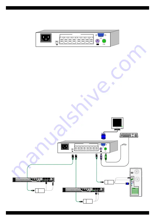
4.  The Smart CAT5 models 

The figure below illustrates the rear panel of the Smart CAT5 16 port unit. The 8 port 
model is the same but with only 8 Computer ports. 

POWER

100-250 VAC 50/60 Hz

1

2

3

4

5

6

7

8

10

11

12

13

14

15

16

9

COMPUTER

www.

mi

nic

om.
co

m


Figure 2 Smart CAT5 16 port rear panel 

5. Pre-installation guidelines 

• 

Switch off all computers 

• 

Place cables away from fluorescent lights, air conditioners, and machines that are 
likely to generate electrical noise 

• 

Ensure that the maximum distance between each computer and the Smart CAT5, 
does not exceed 10m/33ft 

6.  Connecting the Smart CAT5 system 

Connect each computer to the Smart CAT5 system using the appropriate RICC and 
CAT5 cables. Figure 3 illustrates the Smart CAT5 system connections with the 
appropriate RICC connected to a PS/2, SUN and USB computer/server. 

Ke
yb

d

Mo
u

se

1

00T

Vi

d

eo

Se
ria

l A

P

a

ra

lle

l

PCI 33Mx32b

PCI 33Mx32b

PCI 33Mx32b

PCI 33Mx32b

Se
ria

l B

NetServer tc2100

SCSI

Smart CAT5 Switch

SD

P110

PS/2 RICC

USB RICC

SUN RICC

CAT5 cable

Up to 10M / 33ft

CAT5 cables

POWER

100-250 VAC 50/60 Hz

1

2

3

4

5

6

7

8

10

11

12

13

14

15

16

9

COMPUTER

www.

m

in

ico

m

.c

om


Figure 3 Smart CAT5 system connections 

Содержание Smart CAT5

Страница 1: ...el 41 1 823 8000 info europe minicom com Italy Rome Tel 39 06 8209 7902 info italy minicom com www minicom com Customer support support minicom com 5UM20113 V1 4 4 04 Smart CAT5 Switch 8 and 16 Port Q...

Страница 2: ...ents The Smart CAT5 system consists of Smart CAT5 switch 8 or 16 port Remote Interface Connection cables RICCs PS 2 SUN USB CAT5 cables 1 5m provided RS232 Serial cable Rack mounts for the Smart CAT5...

Страница 3: ...e that the maximum distance between each computer and the Smart CAT5 does not exceed 10m 33ft 6 Connecting the Smart CAT5 system Connect each computer to the Smart CAT5 system using the appropriate RI...

Страница 4: ...ed below Connecting a PS 2 RICC Figure 4 illustrates the RICC To computer s keyboard port CAT5 cable to Smart CAT5 Computer port To computer s mouse port To computer s Video card RICC Figure 4 PS 2 RI...

Страница 5: ...e RICC s RJ45 port 2 Connect the other connector to one of the Smart CAT5 s Computer ports 3 Follow the above 2 steps for each computer 7 Connecting the power supply 1 Connect the Smart CAT5 to the po...

Страница 6: ...The OSD is also the place to adjust various settings as explained in the softcopy User Guide located on the Marketing and Documentation CD When switching computers the illuminated LED of the top row...

Страница 7: ...tch side panel POWER 100 250 VAC 50 60 Hz 1 2 3 4 5 6 7 8 10 11 12 13 14 15 16 9 COMPUTER www minicom com 13 Rack mounting the RICCs You can attach the RICCs to a server rack or computer using the Vel...

Страница 8: ...rl Alt F1 Props Left Ctrl Alt F3 Front Left Ctrl Alt F5 Open Left Ctrl Alt F7 Find Left Ctrl Alt F9 Again Left Ctrl Alt F2 Undo Left Ctrl Alt F4 Copy Left Ctrl Alt F6 Paste Left Ctrl Alt F8 Cut Left C...

Отзывы: