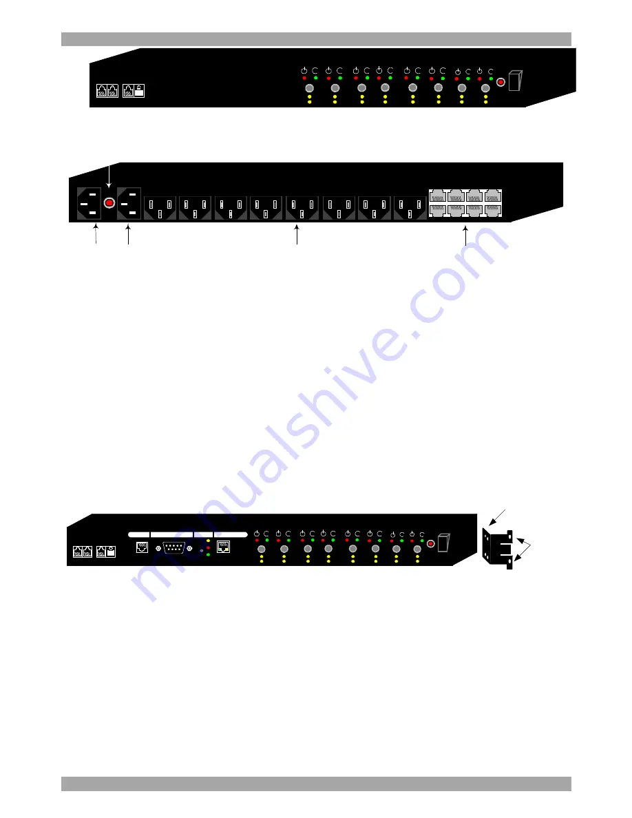
REMOTE POWER SWITCH
4
RING ON
& RESET
iLINK
i
i
i
i
i
i
I
0
A
B
C
D
E
F
H
9
1
10
9
9
11
12
9
5
13
14
6
7
15
16
8
G
i
i
Figure 2 RPS Slave front
INPUT
D
C
B
G
F
H
/
/
/
E
A/
INPUT
H
G
F
E
D
C
B
A
AC input
Circuit
breaker B
Power output
RS232 (safe shutdown)
Figure 3 RPS Manager and Slave rear panel
Note: The letter on the manual buttons at the front corresponds to the outlet with
the same letter at the rear.
5. Rack mounting the RPS
The RPS comes with brackets for mounting onto a standard 19-inch rack.
To rack mount the RPS:
1. Choose a location for the brackets. A notched hole on the vertical rail denotes
the middle of a U slot.
2. Connect the mounting brackets to the unit, using the screws provided. See
Figure 4
RING ON
& RESET
iLINK
i
i
i
i
i
i
ACTION
LINK
RESET
PWR
ENV
MODEM
ETHERNET
I
0
A
B
C
D
E
F
H
9
1
10
9
9
11
12
9
5
13
14
6
7
15
16
8
G
i
i
INTERNET POWER MANAGEMENT
Connect this section to side
of the RPS using 4 screws
Screw to
the rack
here
Figure 4 Connecting the mounting brackets
6. Installing the RPS
You can connect the RPS to a LAN using the Ethernet connection. Another option
is to connect an external modem to the built-in RS 232 port for Internet dial up.
Once set up, the administrator can power the devices on and off via a Web browser.
Connecting the RPS
1. Connect the power cord sockets of the computers and other devices to the
Output ports of the RPS.


