11
3-4. Network ID setting (SW1)
When several modules are connected to one daisy chain network, this switch is to set intrinsic
ID to each module.
* The ID in MODBUS mode is the set value plus 1.
3-5. Termination setting (SW2.2)
Termination resistor is connected internally by setting on SW2.2.
When connecting to the end of the communication network, please
set the termination.
3-6. Setting switch (SW3)
When this switch is kept pressed and the drive is powered on
the drive operates in the Plus-R mode at 115200bps.
The switch’s function after power-on can be programmable. Please
refer to the parameters settings.
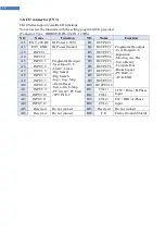
3-7. Power & EMG input (CN1)
Motor power and control power are supplied separately and
the rated current of driving motor is 4A.
Please be careful not to supply only motor power, And use
appropriate power supply and cables.
EMG input can force the drive to stop at emergency.
Please refer to the parameter settings.
(Connector Type : DINKLE / 15EDGRC-3.81-6P)
No
Name
Description
1
F.G
Frame Ground
2
GND
3
DRV-PWR
24/48VDC
4
CTL-PWR
24VDC
5
EMG+
Emergency Stop control
(Use B-contact)
6
EMG-
Position
ID(PR)
ID(Modbus)
Position
ID(PR)
ID(Modbus)
0
0
1
8
8
9
1
1
2
9
9
10
2
2
3
A
10
11
3
3
4
B
11
12
4
4
5
C
12
13
5
5
6
D
13
14
6
6
7
E
14
15
7
7
8
F
15
16


