background image

1

2

3

4

5

6

7

© 2014 MIMAKI ENGINEERING CO.,LTD.

6.2

P.3

R.1.1

 INSTALLATION GUIDE > Power Supply Related > Connecting the Power Cable 

Model

JV400-130/160LX

Issued

2011.02.15 Revised 2013.01.20 F/W ver.

Remark

1.1

Rev.

6.2 Connecting the Power Cable

Outline

This device connects to the included two power cables.
If you do not use the included power cables, use cable that match your region.
Connect the power cables into a power outlet with the following specifications.

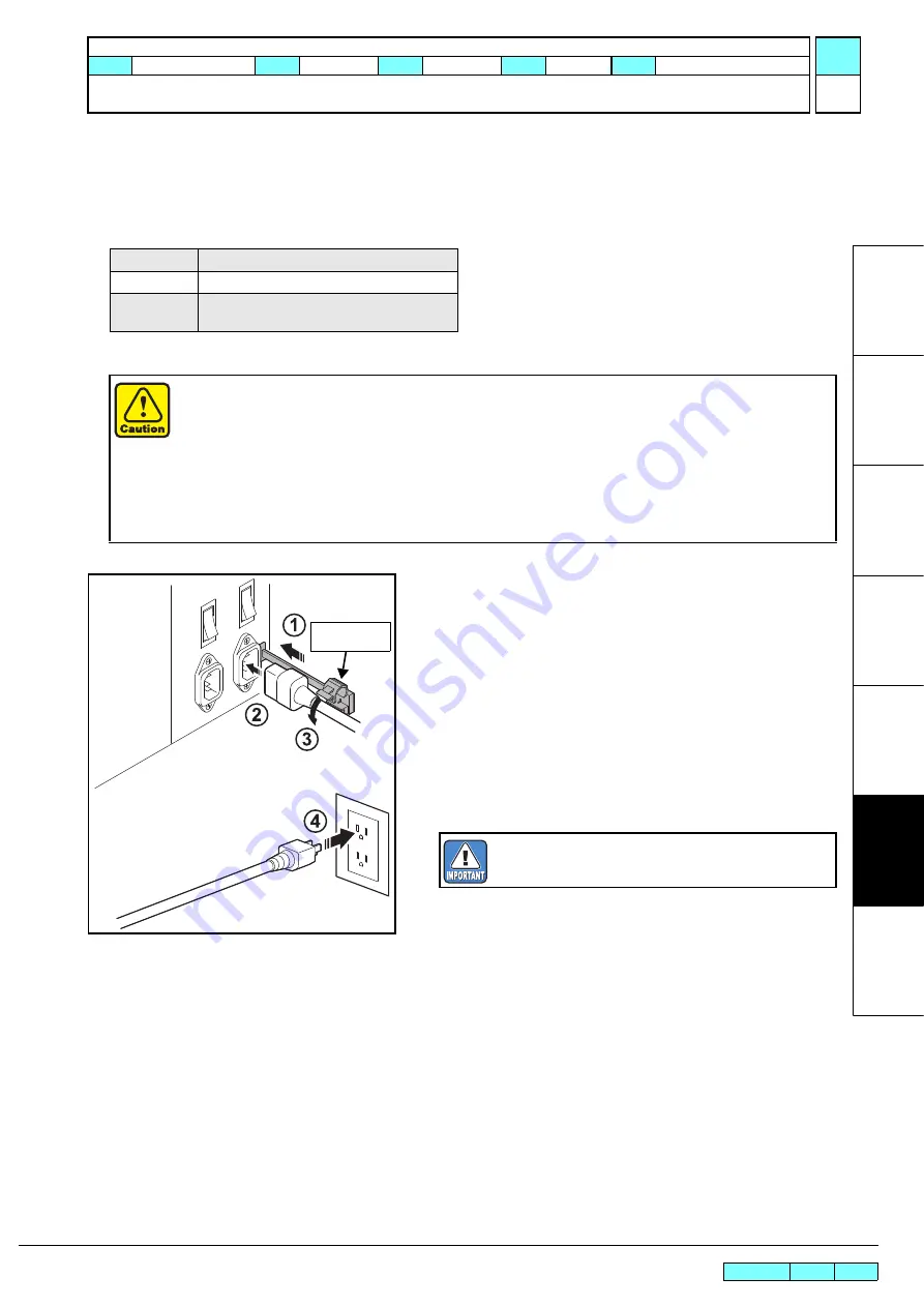
1. Insert the 

power cable clamp

 into the power supply box.

2. Insert the 

power cable

 into the inlet of this device.

3. Lock the power cable.

Run the power cable through the clamp, and lock the clamp 
until it clicks.

4. Insert the 

power plug

 into a plug socket.

Voltage

AC100 to 120V, AC220 to 240V

Frequency

50/60Hz ± 1Hz

Capacity

15A or more (AC100 to 120V ± 10%) x 2 lines
10A or more (AC220 to 240V ± 10%) x 2 lines

Always connect the cables to a power outlet near the device so that the cables can be easily removed.

When plugging the cables into the power outlets, connect the cable into outlets on a separate circuit
from other devices. Because of the large power consumption, the power supply breaker may be
tripped.

Power supply cables should be connected to an earthed outlet. Otherwise, there is a risk of electrical
shock or of damaging the device.

When connecting the power cables, ensure that the power switch of the device is off.

Always connect the same voltage power supply to the inlet1 and inlet2. 

Power cable 

clamp

Insert into the socket of separate power line, respec-
tively.

Содержание JV400-130LX

Страница 1: ...MIMAKI ENGINEERING CO LTD URL http eng mimaki co jp Service Documents D500698 22 JV400 130LX 160LX INSTALLATION GUIDE...

Страница 2: ...Index Rev Changes Revised 3 1 2 Illustration is changed in accordance with heater change Revised 4 1 2 Illustration is changed in accordance with heater change Revised 4 2 P 6 4 2 P 7 4 2 P 9 1 1 Dryi...

Страница 3: ...ed Ink set 6c and 6c W are deleted and 4c W is added Revised 5 1 P 3 1 2 An important item of step 2 is changed Revised 5 2 1 2 The ink label illustration is changed Revised 7 2 P 4 1 2 Step 6 is dele...

Страница 4: ...2014 MIMAKI ENGINEERING CO LTD Change Tracking P 3 Service Documents Change Tracking Change Tracking Date 2011 12 19 Manual Ver 1 00 Remark Status Index Rev Changes Released New issued...

Страница 5: ...e Accessories 4 14 4 5 Removing the Stopper 4 15 4 6 Removing the Fitting 4 16 5 Ink Set 5 1 5 1 Changing the Joints 5 2 5 2 Pasting label on eco case 5 6 6 Power Supply Related 6 1 6 1 Setting the Vo...

Страница 6: ...lection of information for service engineers when setting up JV400 130 160LX inkjet printers During the setup proceed with the work by referring to this document and the following related documents Do...

Страница 7: ...Used Model JV400 130 160LX Issued 2011 02 15 Revised F W ver Remark 1 0 Rev 1 1 Description of the Ink Used Outline Hand the Material Safety Data Sheet MSDS over to the user who will actually use this...

Страница 8: ...phase AC100V to 120V 1440W x 2 Single phase AC220V to 240V 1800W x 2 Power consumption 2120VA or less x2 lines Main unit including heater Installation environment Usable temperature 20 C 35 C In envi...

Страница 9: ...ION GUIDE Installation Space Model JV400 130 160LX Issued 2011 02 15 Revised 2013 04 15 F W ver Remark 1 2 Rev 3 Installation Space 1 000 mm or more 2854 mm or more 500 mm or more JV400 130LX 3634mm o...

Страница 10: ...unting the Accessories Carry out the work to attach the accessories 4 4 p 14 5 Removing the Stopper Remove the stopper 4 5 p 15 In order to prevent accidental cuts always wear gloves when performing d...

Страница 11: ...1 Lift down the carton which contains the stands 2 Remove the lid and sleeve of the box that packages the main unit and take out the Accessories box packing box A and packing box B Box containing the...

Страница 12: ...e units on the roll guide and tighten the take up device unit fixing screws Stand stay Stand stay The stand having the screw holes to fix the tank tray is the right stand Use the hexagonal wrench For...

Страница 13: ...l guide with the Roll guide shuft holding plate Right and left screw M5x15 2pcs Roll holder fixing screw Roll holder Roll holder fixing screw Roll guide Roll holder Roll guide BKT 200A B When attachin...

Страница 14: ...holding plate Right and left screw M5x15 2pcs 10 Lock the four stoppers of the stand Roll guide BKT 200A B When attaching the Roll guide BKT 200A B tighten the screw while pushing the Roll guide BKT...

Страница 15: ...t by removing the screw 12 Using screws CS6x55 8pcs attach the Stay2 to the Main unit 13 Hold the handles of the plotter by four people 14 Put the front face of the stand first Align the screw hole of...

Страница 16: ...upper stand stay on the back of the main unit turning one half with the supplied hexagonal wrench 2 Fitting the screw holes of the main unit and the stand temporarily tighten the screws CS5x15SMW 8pcs...

Страница 17: ...Holder position label 20 Check Clamp Lever is lowered When Clamp Lever is lifted push it down Roll Holder posi tion label Roll Holder Set Position 3 Inch Roll Media 2 Inch Roll Media 30mm 30mm Roll H...

Страница 18: ...ctor at the bottom of the plotter Roll Holder Set Position 3 Inch Roll Media 2 Inch Roll Media Basis Setting position of 3inch tube Setting position of 2inch tube Roll Holder Roll Holder Side Back of...

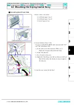
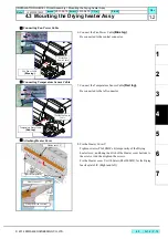
Страница 19: ...ng fan side plate Right and left M5x15 4pcs 2 Fix the Drying Heater Assy on the Drying fan side plate L R Right and left 1 Hook the U groove of the Drying Heater Assy on the positioning screw of the D...

Страница 20: ...r C Tighten the fixing nut of the cable lock firmly 2 Connect the connector 3 Fix a F G cable with a screw 4 Tighten the Cable fixing nut so that a cable does not fall out Slack off the cable so that...

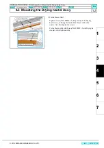
Страница 21: ...n screws P3x8SMW x4 temporarily of the Drying heater Assy and hung the ditch of the Heater cover bottom to the screws And then tighten the screws Fix the Heater cover U with Screw P4x10SMW for the Dry...

Страница 22: ...ng the ditch of the Heater skirt to the screws And then tighten the screws Fix the Heater skirt with Screw P4x10SMW for the Drying fan side plate L R Right and left Heater skirt Heater skirt Hung the...

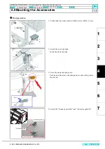
Страница 23: ...the Accessories Work procedures 1 Fix the tank tray to the stands with the screws M5x15 2pcs 2 Attach the waste ink tank Insert the waste ink tank 3 Close the waste ink tank guard Put a hook of the w...

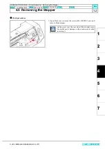
Страница 24: ...JV400 130 160LX Issued 2011 02 15 Revised 2013 04 15 F W ver Remark 1 2 Rev 4 5 Removing the Stopper Work procedures 1 Open Front cover remove the screws P4x 10SMW 1pcs and remove Head stopper Head st...

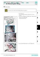
Страница 25: ...cedures 1 Open Front cover Move the Carriage with hand to position easy to work as required 2 Cut the tube at both sides of the fitting which is connected to the tube shown as left hand figure Fitting...

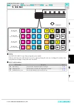
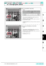
Страница 26: ...e procedure to change to except four color is as below List of work procedures Work operation Description Refer to 1 Head cleaning Celan the inside of head and ink paths to be changed 7 5 p 8 2 Changi...

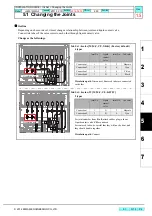
Страница 27: ...W Ink Set 4color M M C C Y Y K K Factory default 4 types Circulation path Disconnect Removed tubes are connected each other Joint No Liquid contact valve Joint No Ink color Connection 1 1 A 2 Magenta...

Страница 28: ...re connected each other Joint No Liquid contact valve Joint No Ink color Connection 1 1 A 2 Magenta Connection 2 3 B 4 Cyan Ink Set 6color White M Or C G Y K W W 0 types For joints number from 1 to 8...

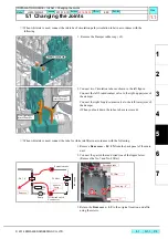
Страница 29: ...e screws Use protective glasses and gloves during work Depending on the working condition ink may reach your eyes or your skin may be roughed due to ink Rear cover LU LX Tube O ring Joint Screw The O...

Страница 30: ...e ink is used connect the tube for white ink filter in accordance with the following 1 Remove Rear cover LU LX from the back panel of the main unit 2 Connect the part of the red dotted line of the fig...

Страница 31: ...depending on ink color to be used Work procedures 1 Paste the same ink color label as the set ink pack on the rear surface of the eco case Paste it by using the right upper corner of the rear surface...

Страница 32: ...ver Remark 1 0 Rev 6 Power Supply Related List of work procedures Work operation Description Refer to 1 Setting the Voltage Selector Set the Voltage Selector 6 1 p 2 2 Connecting the Power Cable Conn...

Страница 33: ...Revised 2013 04 15 F W ver Remark 1 1 Rev 6 1 Setting the Voltage Selector Outline The device voltage should be switched to 100 to 120V or 220 to 240V to match the power supply voltage 1 Switch the v...

Страница 34: ...clicks 4 Insert the power plug into a plug socket Voltage AC100 to 120V AC220 to 240V Frequency 50 60Hz 1Hz Capacity 15A or more AC100 to 120V 10 x 2 lines 10A or more AC220 to 240V 10 x 2 lines Alway...

Страница 35: ...ng the Power On 1 Turn on the main power supplies of this device Move the power supply switch on the back panel of this device to to turn on the main power supply 2 When you press the power switch at...

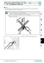
Страница 36: ...hat the head is in the capping station 1 Press the power switch on the front of the device once If you turned the power off without performing capping turn the power back on again Return the head to t...

Страница 37: ...ration Description Refer to 1 Setting at Startup Set the language and the power supply voltage 7 1 p 2 2 Initial Ink Fill Perform ink initial filling 7 3 p 4 3 Test Print Perform test print to check t...

Страница 38: ...selection item Select ENTER Register 4 Set the power supply voltage Select depending on the connected power supply voltage of the machine Select ENTER Register The setting value is as below Area of 10...

Страница 39: ...EERING CO LTD 7 2 P 3 R 1 0 INSTALLATION GUIDE Outputting Plots Pressure Adjustment Deleted Model JV400 130 160LX Issue 2011 02 15 Revised 2012 10 15 F W ver 1 00 Remark 1 0 Rev 7 2 Pressure Adjustmen...

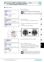
Страница 40: ...been completed 6 Remove air Filling head air port With the key move to the air purge sequence When you press the key air purge work is not performed and the machine moves to the cleaning operation to...

Страница 41: ...orts of the damper selected in 7 press the ENTER key to stop sending ink 2 Remove the ink filling jig and close the cap 12 Press the ENTER key to return the carriag to the position that close the cap...

Страница 42: ...e opening shaft with a flathead screwdriver to the original status Press the key to terminate the operation 15 When you press ENTER the cleaning operation starts When the cleaning operation has been c...

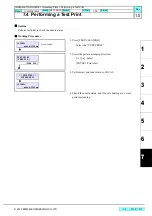
Страница 43: ...Test Print Outline Perform test print to check the nozzle status Working Procedures 1 Press TEST CLEANING Select the TEST PRINT 2 Select the pattern arranging direction Select ENTER Print start 3 Perf...

Страница 44: ...recover from nozzle missing and deflection Working Procedures 1 Press TEST CLEANING twice Select CLEANING 2 Select the cleaning type Select ENTER Register 3 Select the head to clean Start the cleaning...

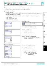
Страница 45: ...and scanning speed WF1 900N 1200N WF2 900N 1200N 900H 1200H WF3 600N 600H for only LX100 1 Set Media at X origin 2 Display ADJUST PRINT ADJUST 3 Select the waveform Switches ENTER Confirms Next 4 Sel...

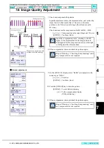
Страница 46: ...sation display Without drawing 11 When compensated draw and check the patterns again 900Hi SiDir WF1 H1A H1B 0 0 99 9 99 9 900Hi SiDir WF1 H1A H1C 0 0 99 9 99 9 Magnify by a microscope and measure it...

Страница 47: ...fixed Confirm that the dots are on the same line The adjusting procedure is the same although the drawing pattern is different depending on mode Compensating value input Measured value ENTER Confirms...

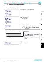
Страница 48: ...LOCAL width 1000mm ADJUST FEED COMP ENT FEED COMP PRINT ENT PRINTING PLEASE WAIT FEED COMP 0 Second band First band Media advance direction FEED COMP pattern Print two bands as the compesation pattern...

Страница 49: ......

Страница 50: ...D500698 22 30042014 2013 MIMAKI ENGINEERING CO LTD KF FW 2 50...

Отзывы: